 Grant Giesbrecht
For the compressor to work correctly, the input signal's amplitude must be set correctly. A graph of input vs output amplitude of the compressor help to illustrate why.
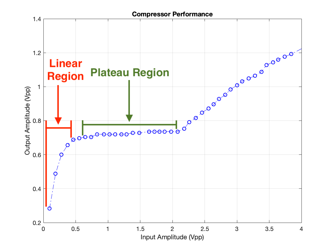
As you can see, there is a region in which input and output amplitudes are correlated roughly linearly. There is also a region in which input amplitude can change greatly but output amplitude stays nearly constant. These linear and plateau regions fundamentally are why the input source's amplitude must be correctly adjusted; when listening to an audio signal you don't want the compressor to level the volume unless something comes through which is far too loud (otherwise pauses in speaking or music would be amplified to the same level as level as the primary content). In other words, unless a sudden loud noise comes your way, you don't want to notice the compressor - you want a linear relationship between input and output amplitudes - you want constant gain. The circuit should be operating in the linear region typically. Only when a loud signal comes through that needs to be compressed should the circuit enter the plateau region. The peak indicator I describe in this log indicates to the user via an indicator light when the circuit is transitioning from the linear to the plateau region. In typical use, the user would set the input source volume to the maximum which doesn't illuminate the peak indicator.
As for the actual design, ideally the indicator would be triggered based on the voltage which determines the compressor's gain (Q1's base voltage) because this is exactly the parameter which determines if the circuit will behave linearly or non-linearly. I chose to base my indicator on the input amplitude, however, because Q1's base voltage changes by only a few millivolts between the beginning of the linear region and the end of the plateau region. Even an offset of a few millivolts in the indicator's calibration could cause the indicator's trigger level to be off by a volt or more. Comparing the input voltage against a carefully selected reference voltage is a much more resilient technique.
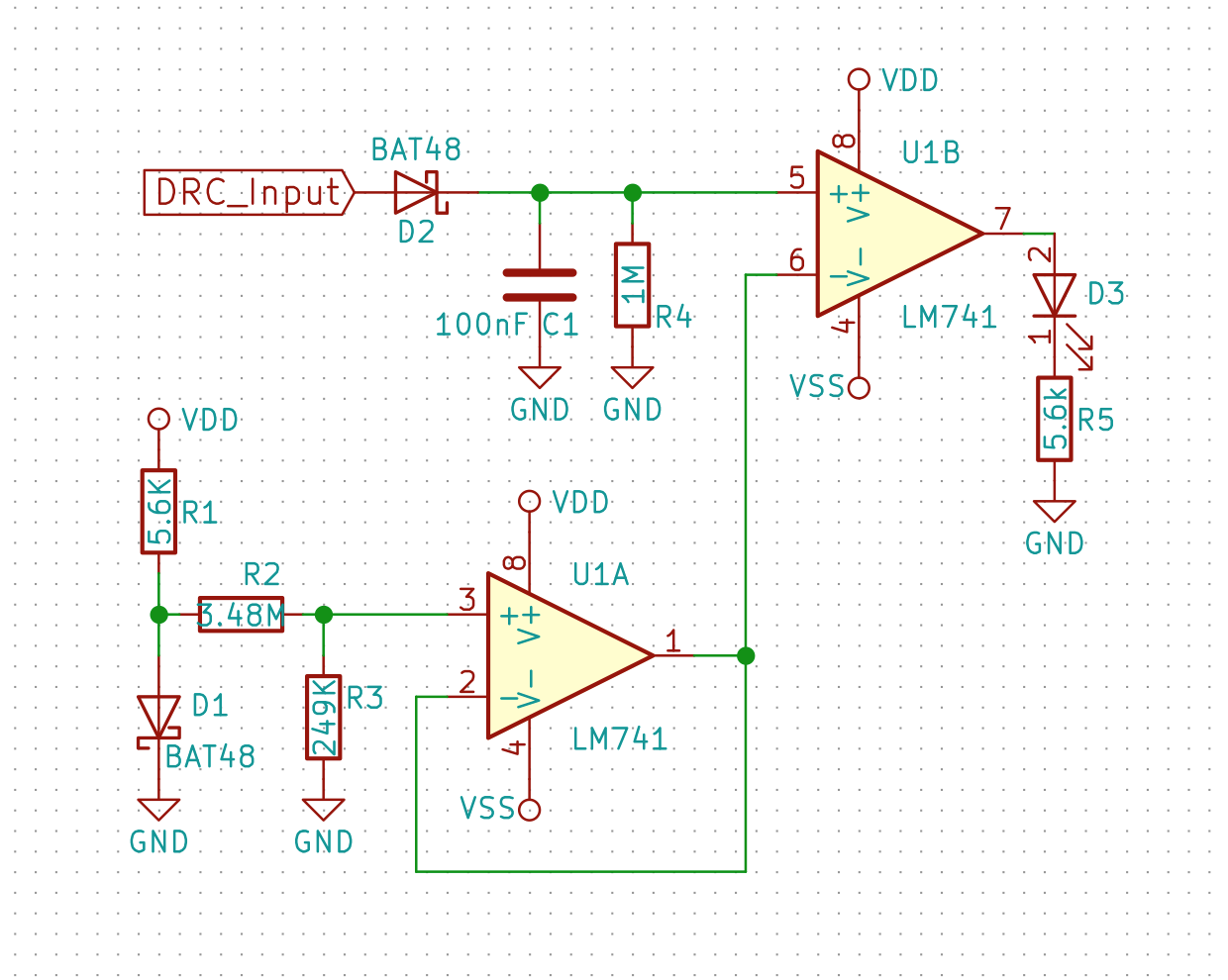
The only catch is generating the reference voltage. A voltage reference is called for here, but I didn't have one on hand so I decided to use a diode's forward voltage instead. I'll need to change this eventually, however. Here's what I came up with:
 One of the most important aspects of the voltage reference (or in this case, what I'm using in place of a reference) in this circuit is that the voltage is constant regardless of supply voltage. Because the device has a very wide input voltage range (about 4-5V on the low end (this is the output voltage of a 9V when it's towards the end of its life) and 12V on the high end (12V DC jacks are pretty ubiquitous and need to work with the equalizer's DC jack) ) the reference needs to produce an approximately steady voltage with an input range of 4-12V. I took measurements of the threshold voltage, ie. the voltage at which the indicator turns on - the voltage from the "reference", vs supply voltage.
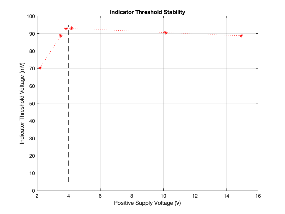
Although the data look damning at first glance, the results are actually quite acceptable for this application. The device should only ever be operated between 4 and 12V. These bounds are indicated in the graph by the dashed lines. Between these limits the threshold voltage only changes by about 3mV as opposed to ~23mV variation over the full tested range. Naturally the question becomes "how precise does the threshold voltage need to be?", and the answer is "not very" because we're comparing against the input voltage. The transition between the linear and plateau regions is not crisp so where the indicator's threshold should lie exactly is somewhat arbitrary. Furthermore, the transition between these two regions spans around 100mV, so a 3mV change will move the indicator's threshold through only a tiny fraction of the transition region (about 3%). Conclusion: this crude solutoin seems to be more than good enough. I didn't test threshold voltage variation against temperature change (which it absolutely will depend on, due to the diode junction voltage changing with temperature) because I had neither the resources to do this, nor the motivation. I'll be replacing this with a voltage reference in the end, so it's exact performance characteristics need not be precisely defined.
Discussions
Become a Hackaday.io Member
Create an account to leave a comment. Already have an account? Log In.