 Grant Giesbrecht
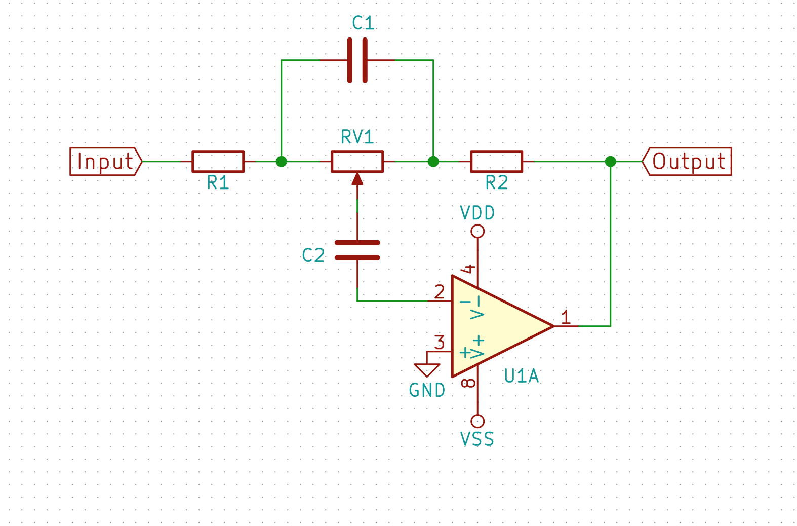
Before getting into the nitty-gritty of designing the equalizer such as selecting component values or specific op-amps I needed to select a topology. The multiple-feedback topology was appealing because it is well-known and equations are available that can give you a circuits with a specified Q and cutoff frequency. This makes it comparatively easy to get a multiple-feedback filter that produces a pre-selected frequency response. I decided not to use this topology, however, because I saw no clear way to adjust the gain from its maximum gain smoothly down to a minimum gain that is exactly the inverse of the maximum gain. A more attractive alternative was a topology that first appeared (to my knowledge) in a Philips application note from 1984, AN142 "Audio circuits using the NE5532/3/4". The Philips topology is a modified form of a typical op-amp inverting amplifier that uses a potentiometer in the feedback network to select gain, and capacitors either bypassing or in series with the potentiometer to ensure that it is only effective at setting the gain above or below unity at specific frequencies. The fundamental design is shown in the schematic below.
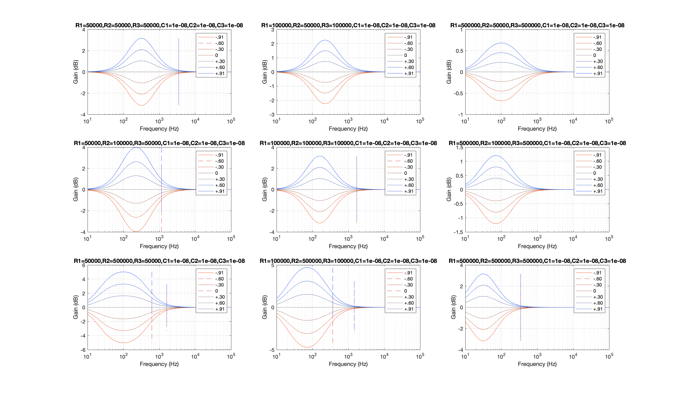
One drawback with this circuit, however, is that convenient design equations aren't available. I started analyzing the circuit by hand, but bringing the algebra through to a point where I could get a formula for Q and cutoff frequency proved to be more trouble than it was worth. I decided instead to analyze it only qualitatively on paper (to build an intuition for how it works and how to modify its transfer function), then simulate it in MATLAB. I wrote a program that would generate 9 bode plots for the circuit, each with a different set of values. I used that to confirm that my qualitative analysis was correct, and to determine quantitatively which values I should test on a breadboard.
Using this methodology, I decided to try for the low-band circuit the Philips topology with fixed resistors of 500Ω, a 100KΩ potentiometer, and 600nF across the potentiometer. C2 was omitted and shorted because C2 would diminish low-frequency gain. I chose 100KΩ for the potentiometer because I already have a nice 2-gang potentiometer from GEQ-1 picked out for this project with a 100kΩ resistance.
Initial measurements of the transfer function were encouraging. They aligned very closely with the predicted measurements. Of course, what really matters is how it sounds, so I listened to some music through the circuit as well. I tested a couple changes, but the only change I kept in the final design was changing the capacitor's value to 800nF to decrease the cutoff frequency and make the filter's gain closer to unity at higher frequencies.
Discussions
Become a Hackaday.io Member
Create an account to leave a comment. Already have an account? Log In.