 Grant Giesbrecht
Before starting this project I had tested a compressor circuit W2AEW discussed on his Youtube channel. The circuit used a peak detector to set the quiescent current through a germanium diode which was used as the lower-half of a voltage divider. The voltage divider sets the gain of the circuit (which, of course, is always below unity). Although W2AEW was able to get admirable performance from his circuit, I wasn't able to replicate his success. I had more success using the circuit shown below.
One aspect of the new circuit I prefer over W2AEW's circuit is that the new design utilizes a closed-loop control system as opposed to the open-loop system in W2AEW's circuit. I decided to go with the closed-loop circuit instead of W2AEW's circuit for two reasons: 1.) in practice, I was able to get better results from the closed-loop circuit 2.) the closed-loop circuit is made from commonly available components, whereas the other requires the somewhat rare and difficult to obtain 1N34A germanium diode. Although W2AEW's circuit could be made form non-germanium diodes, it's performance would be worse and it would be more difficult to correctly adjust due to the steeper I-V characteristic curve of Si diodes compared to Ge diodes.
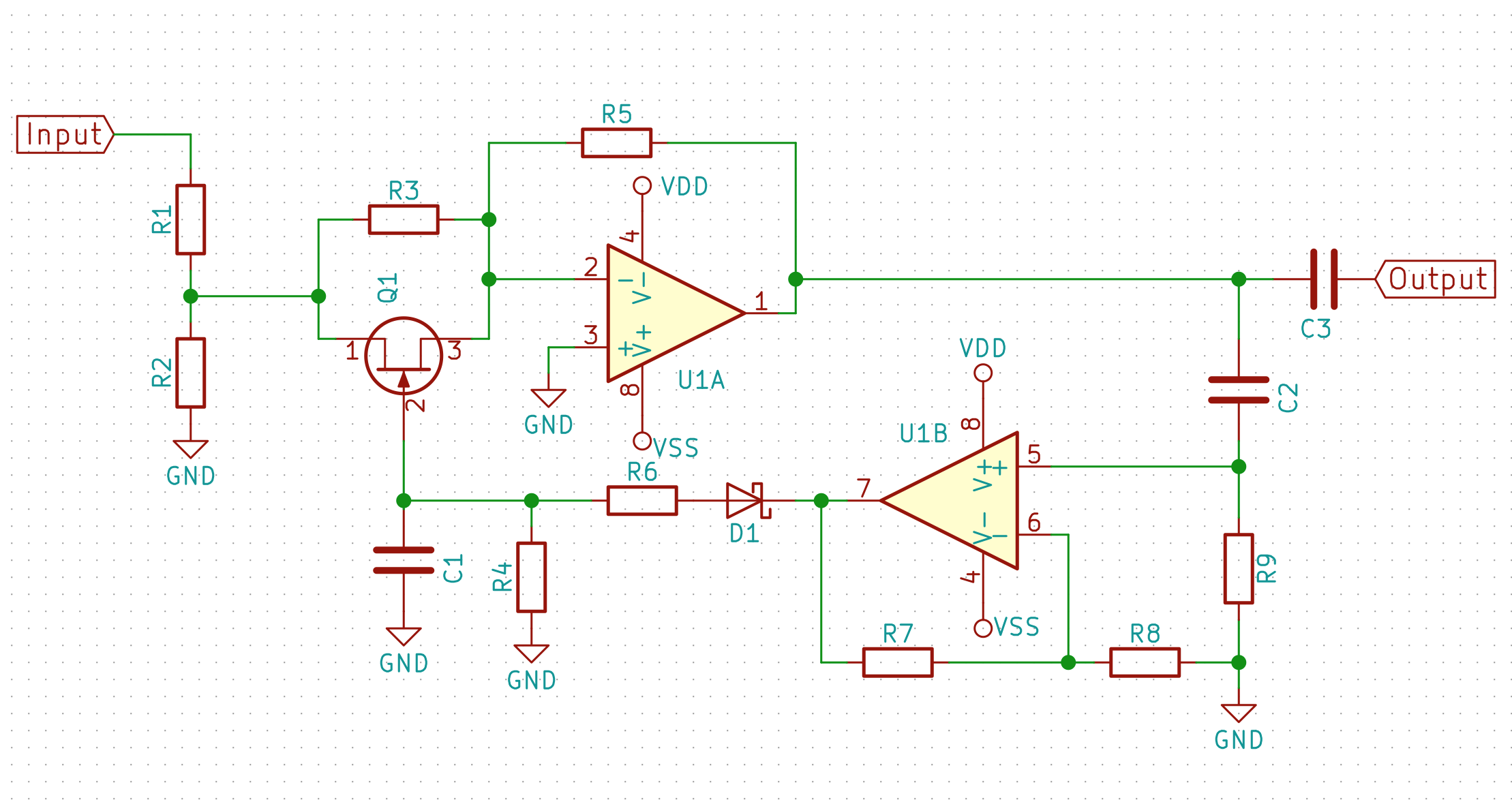
As I was tweaking the closed-loop circuit to work with my equalizer I ran into issues with the output amplitude oscillating. The oscillations occurred because the feedback was too strong. U1B's gain was set much too high, which caused a cycle in which first U1A's gain would be way too low because U1B would perceive the output signal as too large, then the output amplitude would drop to near zero, at which point U1A's gain jumps up way too high. Reducing U1B's gain solved this problem. The circuit was working correctly to stabilize the output signal amplitude.
I added clipping diodes to the output of the circuit (an idea I borrowed from W2AEW's design) to help attenuate any sudden changes in volume which the main feedback system would be too slow to catch. However, listening to audio signals through the circuit showed that it was negatively impacting sound quality. I realized that the attack time (how long it takes for the circuit's gain to change to counter a change in output amplitude) was too fast, causing the circuit to change its gain continuously as music played rather than just when the volume changes dramatically. Increasing C1 and R6 slowed the attack time and fixed the problem. There was no discernible change to audio signals passed through the circuit.
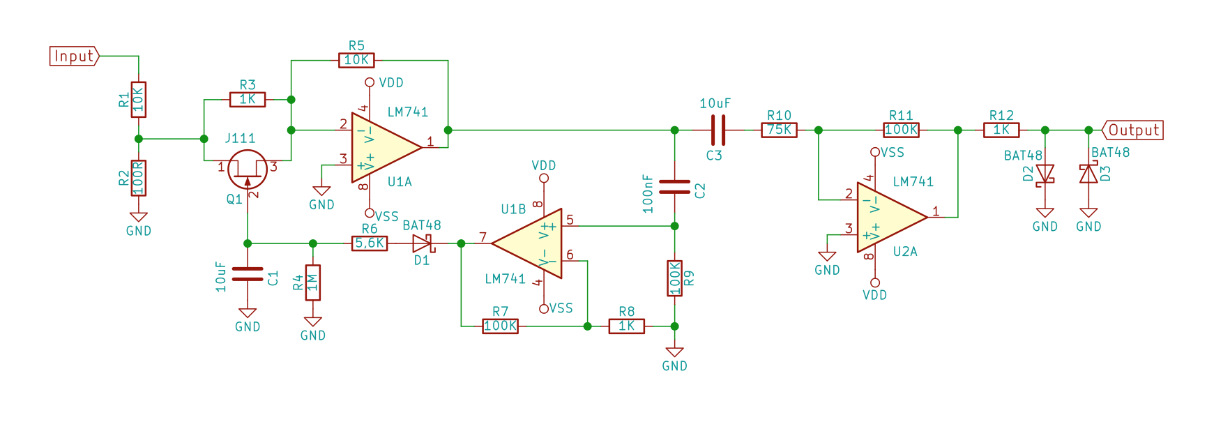
Lastly, I added a fixed-gain amplifier at the output of the compressor to restore the signal level's amplitude back to that before the compressor. The finished circuit is shown below.
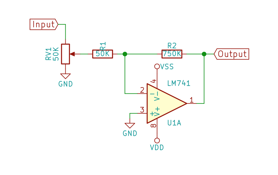
Lastly, I added an amplifier to the output with a potentiometer to set the total gain. This will serve as the master volume control.
Discussions
Become a Hackaday.io Member
Create an account to leave a comment. Already have an account? Log In.