Prelude:
A Chinese knockoff battery charger fell into the shopping basket while ordering some electronic toys from a Chinese vendor.
Don't turn it on, take it apart.
Inside there is an MCU with all markings removed. The Internet is also guessing about brand and type of the MCU used in those chargers.
Ok, now you got me interested.
Guesswork, consulting datasheets, googling through Internet forums and comparing pinouts leads to a device MC96F6432 from ABOV (a Korean company, http://www.abov.co.kr) as a likely candidate. There are datasheets and documentation available for these MCUs, however the information about the ISP/debug interface (OCD) is very limited (not to say incomplete and inaccurate). With some (documented) logic-level wiggling on the OCD pins we managed to get the MCU into debug mode after power up, but not much further due to the sparse information in the datasheet. As this confirms our guess about the used MCU brand and family, it’s time to take it to the next level: learn about the OCD protocol and how to use it.
The ABOV MC96F family consists of an 8051 core with additional FLASH, external RAM and quite some extra on-chip hardware and would make an interesting candidate for some small hardware projects. Thus, the lack of open source tools to program and debug this device is somewhat “irritating”, so we are about to change that...
Act 1: first steps
Let’s go shopping:
- Some ABOV MC96F6432 MCUs to play around with - check
- PLCC adapter boards - check
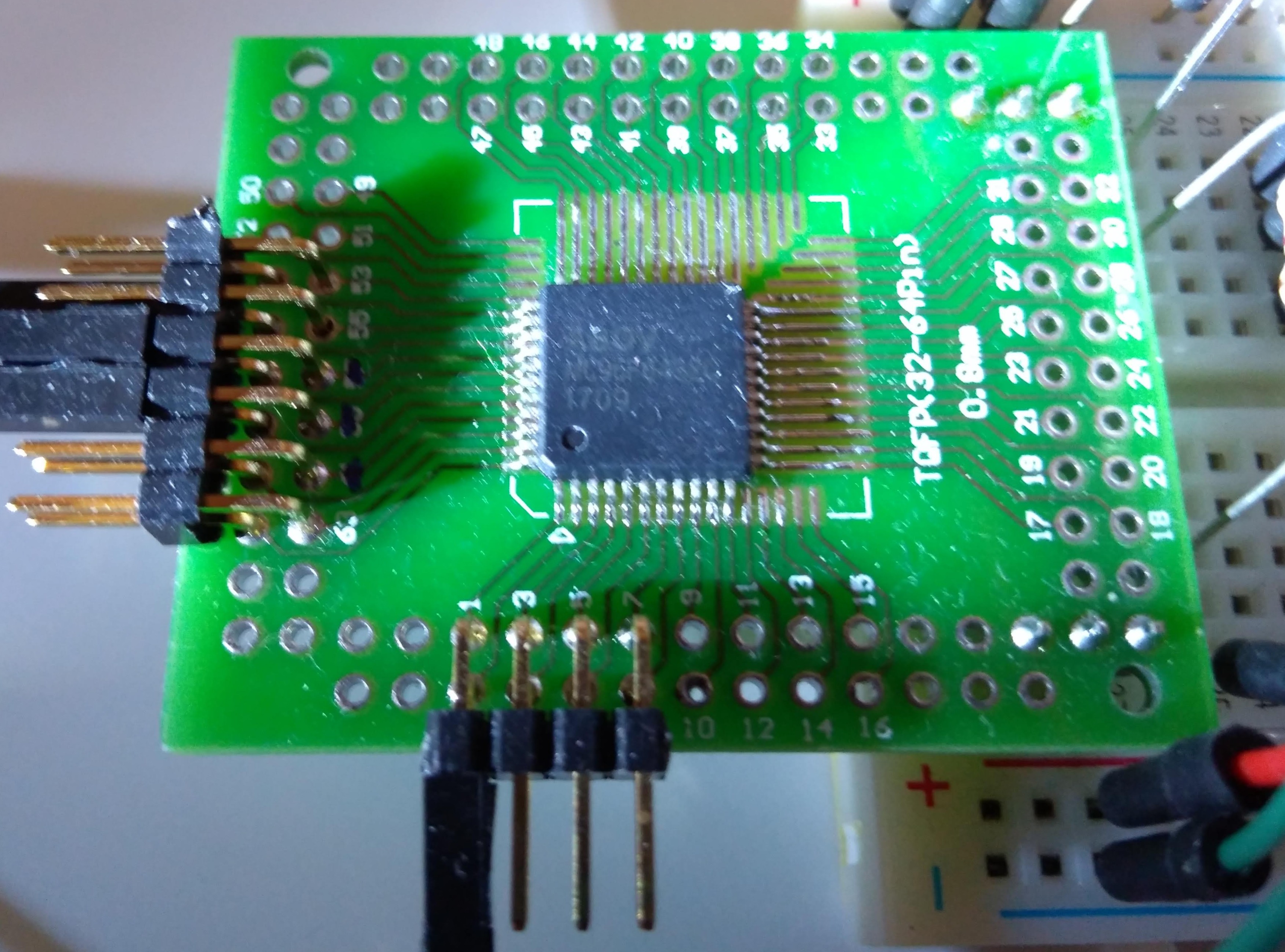
Other equipment, such as a Buspirate, logic analyzer and spare Arduinos boards are part of every reasonably equipped lab - or should be.
As mentioned, the documentation in the ABOV data sheets covering the OCD interface is superficial and is missing quite some relevant information. Rather quickly we had to accept that approaching our project from this side would not succeed. And this is the part where the real fun is about to start.
Reverse engineering - the art of getting to understand a black box (or partial black box).
Challenge accepted.
Act 2: to reverse engineer something you need something to reverse engineer
OK, we need an OCD adapter and get the official software working, then start to reverse engineer the OCD communication. Searching for an ABOV OCD adapter shows that they are hard to find in Europe.
But it turns out that ZILOG has a very similar MCU family... Even the datasheets are basically 1:1 copies of the ABOV documents (some diagrams even have not been rebranded properly and still show the ABOV brand). Even the downloadable Windows software for the OCD adapter looks the same. Soo... let's assume that those MCUs are compatible/identical. It actually looks like the ZILOG chips are just rebranded ABOV MCUs.
We organized two sets of Zilog OCD adapters, one original ZILOG OCD adapter and one ET-Z8051 OCD adapter, ordered from an Asian supplier. Both OCD adapters are working with the ZILOG software, but both adapters refuse to work with the ABOV software.
Act 3: reverse engineering the tools we want to use to reverse engineer
So we tak a detour in first reverse engineering the OCD adapters - void the warranty!
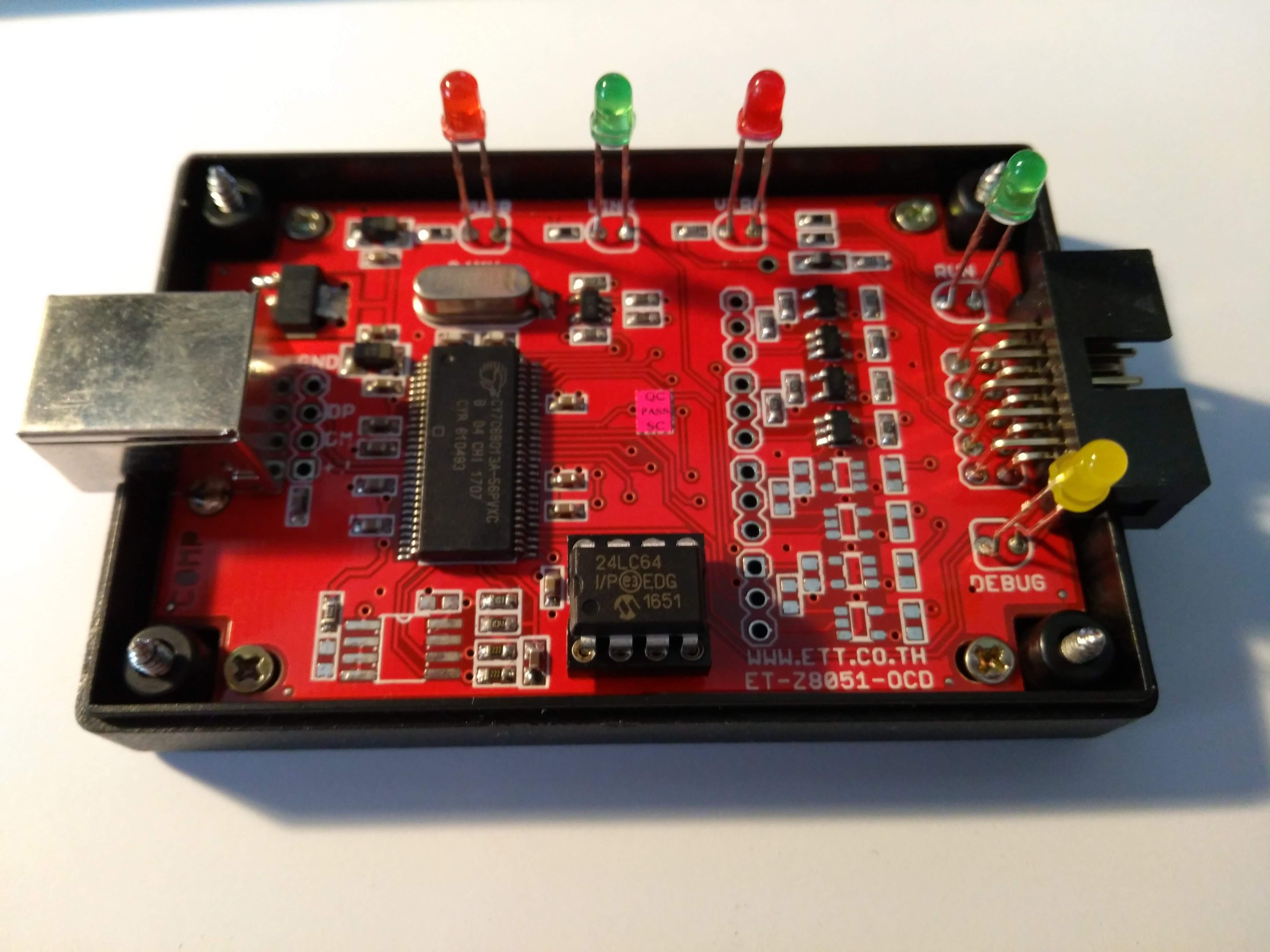
ET-Z8051 OCD adapter:
Zilog OCD adapter:
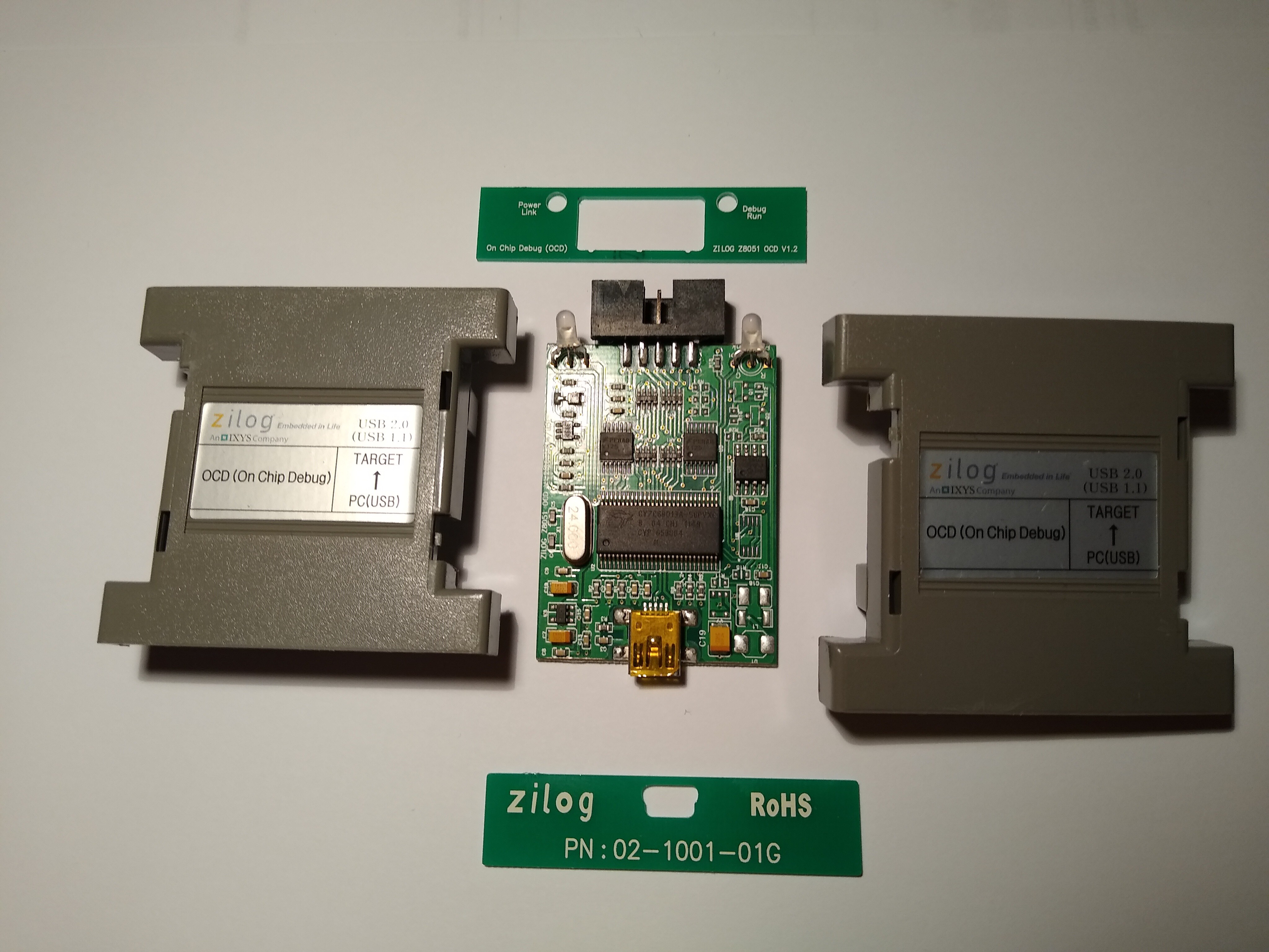
There is a Cypress EZ-USB chip inside. So let’s look for Cypress documentation and learning about those chips and their firmware/boot behavior. A first educated guess is that the only differences between a ABOV and a ZILOG OCD adapter are the USB vendor and product IDs. Cypress provides really good documentation about their hardware. After reading some of the available Cypress documentation about the boot procedure it is evident that the USB vendor and product IDs are stored in the attached i2C EEPROM and the firmware image is downloaded by the driver. The VID/PID used by ABOV and ZILOG are different and exposed in the Windows drivers .inf files.
So, we could just pop out this EEPROM and read/reprogram it - but that would be almost too easy. There must be another, more elegant way - and yes, again the excellent Cypress documentation and support forum point the right direction. Cypress SDK software and a special firmware (Vend_Ax) allow EEPROM access via USB vendor extensions. However, this requires the modification in the .inf files of the cypress driver and requires driver signatures to be disabled in Windoze - just ugly. It turns out that there is a surprisingly easy Linux way - fxload. This is a firmware download utility for Cypress based USB devices. Together with the mentioned firmware image (Vend_Ax) that implements a few USB vendor extensions to read/write access a connected I2C EEPROM, fxload allows also reprogramming the USB vendor and product IDs in the EEPROM. The only feature missing is to read the EEPROM content. But hey, it’s open source!
Forked and added the feature to dump the EEPROM content. Now we can take a ZILOG OCD adapter, reprogram its VID/PID to impersonate the ABOV device. The ABOV drivers are happy, the adapter is detected by the ABOV software and communicates via the OCD interface with our MC96F6432 MCU.
Act 4: a small detour in tool making
Reverse engineering the communication (which has some similarities with I2C) requires a tool to capture and display the data on the line in a human readable form. We do not want to lose time with bit counting binary decoding - an ideal task for a logic analyzer. It is time to undust and power up that Saleae Logic16 sitting on the shelf. The excellent Logic software (supporting Linux of course) comes with an SDK to implement your own protocol analyzers/decoders…
So we build a new protocol analyzer/decoder plugin to handle the ABOV OCD protocol. Most information (command structure, read/write command codes, memory targets) can be found in ABOV datasheets, some undocumented codes and sequences have to be guessed.
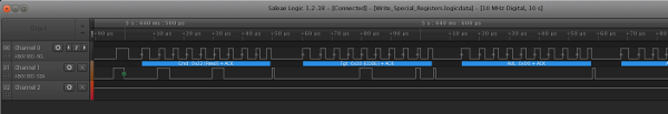
Finally we are able to capture the OCD communication and decode it with little effort.
Act 5: find a cheap and easy way to build your own OCD adapter
Our goal is: everybody shall be able to program those ABOV MCUs without exotic or expensive hardware or software. A cheap adapter hardware (available anywhere in the world) and (forget that fancy, colored GUI) a command line tool that runs on Linux it shall be.
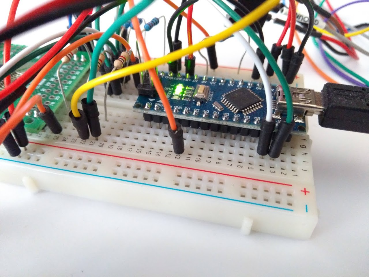
First experiments with a Buspirate in binary bit-bang mode fail miserably due to being too slow, the latency on the serial via USB communication is just too big. Scrap that. The next choice is to use an Arduino nano as adapter - it is available anywhere in the world for just a few dollars. With the right firmware, all the time critical line handling can be managed easily on the Arduino board. This approach works just fine. All time sensitive line handling and signal toggling is done by the Arduino, a separate PC utility contains the logic and user interface (Unix style UI = CLI of course). Now as the tools are ready we can run the ABOV programming tool and capture the OCD communication with a Saleae Logic. Analyze what is read/written, identify the relevant sequences and implement them into our z51dude.
 Schematic with remote power capability:
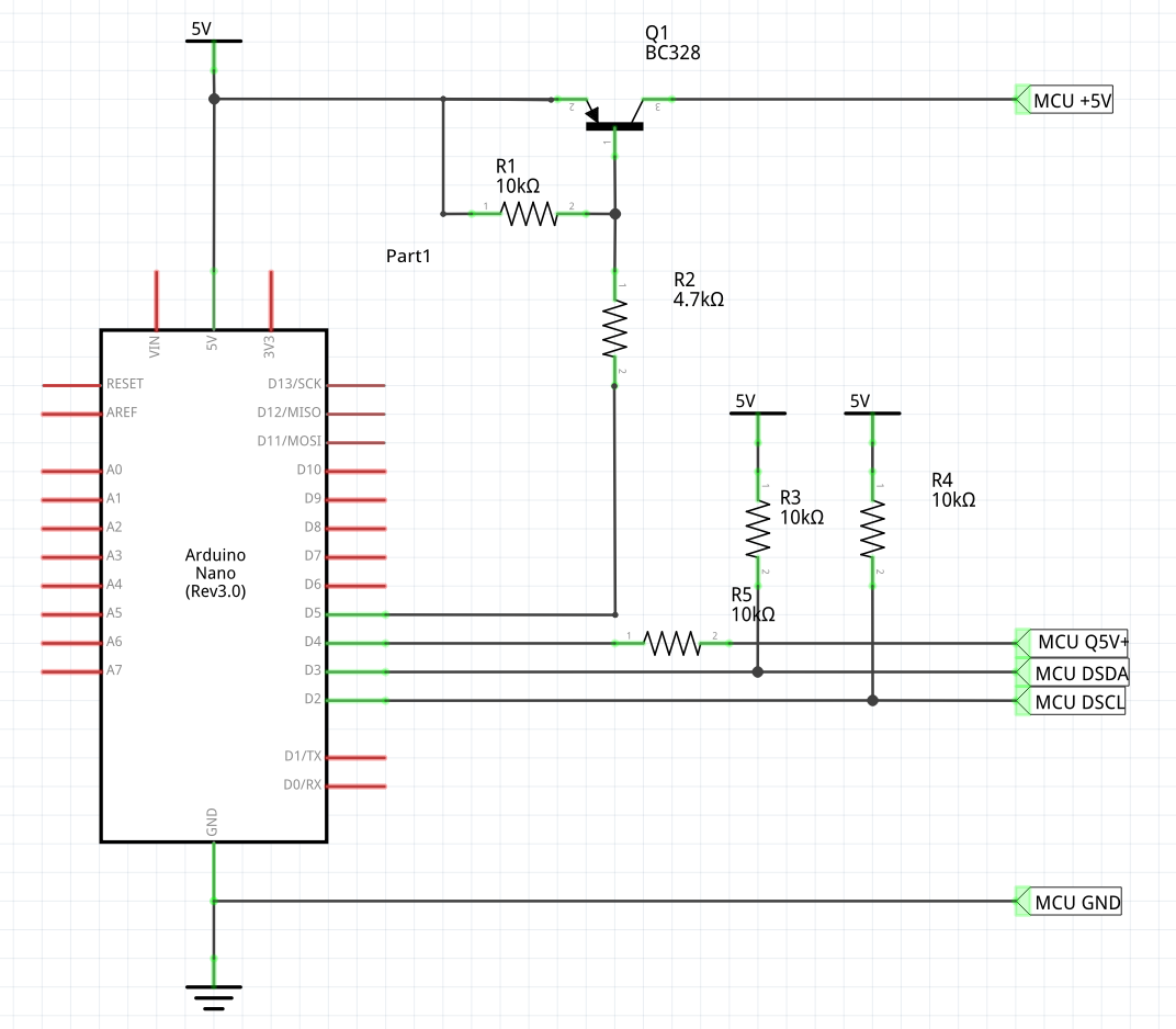
There is still a number of unknown and undocumented registers (did we mention that the ABOV documentation covering that part has room for improvement?) in the debug controller - but the basic functions such as flash reading/erasing/programming, reading and writing RAM and SFRs, program execution control (start/stop/single step) do work.
In the referenced GitLab repository there is everything needed to build the Arduino firmware and z51dude, as well as the Saleae Logic Analyzer plug-in code.
Currently a limited number of MCUs are marked as supported (as we were able to test them with z51dude). Further MCUs may be added in the future - sending us some MCU samples may set priorities and speed up this process.
GitLab Repository is here