Sponsor Link:
UTSource.net Reviews
It is a trustworthy website for ordering electronic components with cheap price and excellent quality.
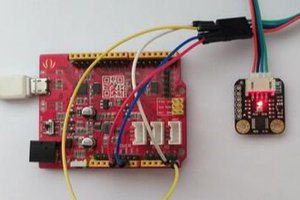
Mounting the circuit
This project's circuit is so simple that you won't even need a breadboard at all. The input dust sensor connects directly to the Arduino microcontroller with three jumper wires. As a precaution before starting, remove any electrical power source through your Arduino. Then, connect the yellow wire (signal) on the dust sensor to D8 (digital pin 8) on your Arduino board through the JST connector. After, connect the red wire (VCC/+) of the sensor's JST connector to the 5v (+5 volts) which is located on your Arduino power pins row. Lastly, connect the black wire (GND/-) from your Grove Dust Sensor, again, through the JST, to one of your Arduino's GND (-) pins. That is it for the hardware setup regarding this project!
Arduino Grove - Dust Sensor (PPD42NS) Project Code
int pin = 8;
unsigned long duration;
unsigned long starttime;
unsigned long sampletime_ms = 2000;
unsigned long lowpulseoccupancy = 0;
float ratio = 0;
float concentration = 0;

void setup() {
  Serial.begin(9600);
  pinMode(8,INPUT);
  starttime = millis();
}

void loop() {
  duration = pulseIn(pin, LOW);
  lowpulseoccupancy = lowpulseoccupancy+duration;
  if ((millis()-starttime) >= sampletime_ms) //if the sampel time = = 30s
  {
    ratio = lowpulseoccupancy/(sampletime_ms*10.0);
    concentration = 1.1*pow(ratio,3)-3.8*pow(ratio,2)+520*ratio+0.62;
    Serial.print("Concentration = ");
    Serial.print(concentration);
    Serial.println(" pcs/0.01cf");
    Serial.println("\n");
    lowpulseoccupancy = 0;
    starttime = millis();
  }
}
About the code
This code consists of multiple functions which is really helpful in Arduino, especially when dealing with complex sensors and interfaces. This code starts off with declaring a pin for this sensor, which is D8 (digital pin 8) as an integer. For the next two lines, we declare extended size variables for number storage only. It can be used later to assign values or readings to that variable. We can write and store data in unsigned long variables such as data coming out from sensors, math calculations, readings over time, etc.. The variables in those two lines are: duration and starttime. Moving on, there are additionally two more unsigned long variables with a reading currently assigned (sampletime_ms and lowpulseoccupancy), it will be used further down the code. The benefit with these variables are that they can carry more data as they have extensive size, proving to be useful in gathering data. The following float variables (ratio and concentration) are for decimal numbers so with a pre-set value declared, it could be used to read decimal numbers later in this sketch. Now, we move onto the void setup section, beginning with setting up the serial communication to output data from the sensor at a rate of 9600 bauds. Followed by the next line, we set D8 (digital pin 8) as an input pin, so that data from the sensor will be sent to the Arduino microcontroller. After, we command the variable, starttime, to read the current time in milliseconds, so that the variable can be involved with timing, further down the lines. That is it for the setup section, and now, it is time to get into the void loop part. The first line of the void loop is one of the Advanced I/O functions where it reads the pulse, whether it is HIGH or LOW (1 or 0). In this code, the pulseIn function is set LOW, so this function will start timing the LOW pulse until it changes to HIGH. Following that function, the time collected will be assigned to the unsigned long variable of duration, reading the time in microseconds. Now, we declare the variable of lowpulseoccupancy to read its own reading itself, plus the readings of the variable duration. We...
Read more »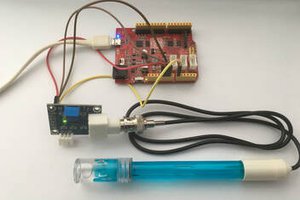
 Nevyn
Nevyn