0%
0%
Hackerbot : MakerBot Replicator+ with RAMPS/Marlin
Turn your Makerbot Replicator+ into a full open hardware 3D printer
 samuel.heidmann
Become a Hackaday.io member
Already have an account? Log in.
Just one more thing
To make the experience fit your profile, pick a username and tell us what interests you.
Pick an awesome username
hackaday.io/
Your profile's URL: hackaday.io/username. Max 25 alphanumeric characters.
Pick a few interests
Projects that share your interests
People that share your interests


 Lys-0929
 Electronx
 Stephen Hayes
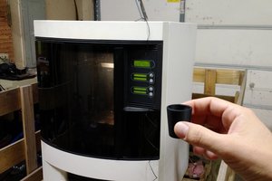
 CaptMcAllister
What a fantastic tutorial. Thank you for sharing this. I plan to do something similar to my Makerbot 5th gen and will certainly reference this. I just hope it's as easy as you make it seem :)