 Matt Bradshaw
The fifth iteration of the DrumKid PCB arrived from China this week, and I'm pleased to report that it pretty much works! I had changed and added quite a lot since V4, so there were always likely to be a few problems, but overall I'm pretty happy.
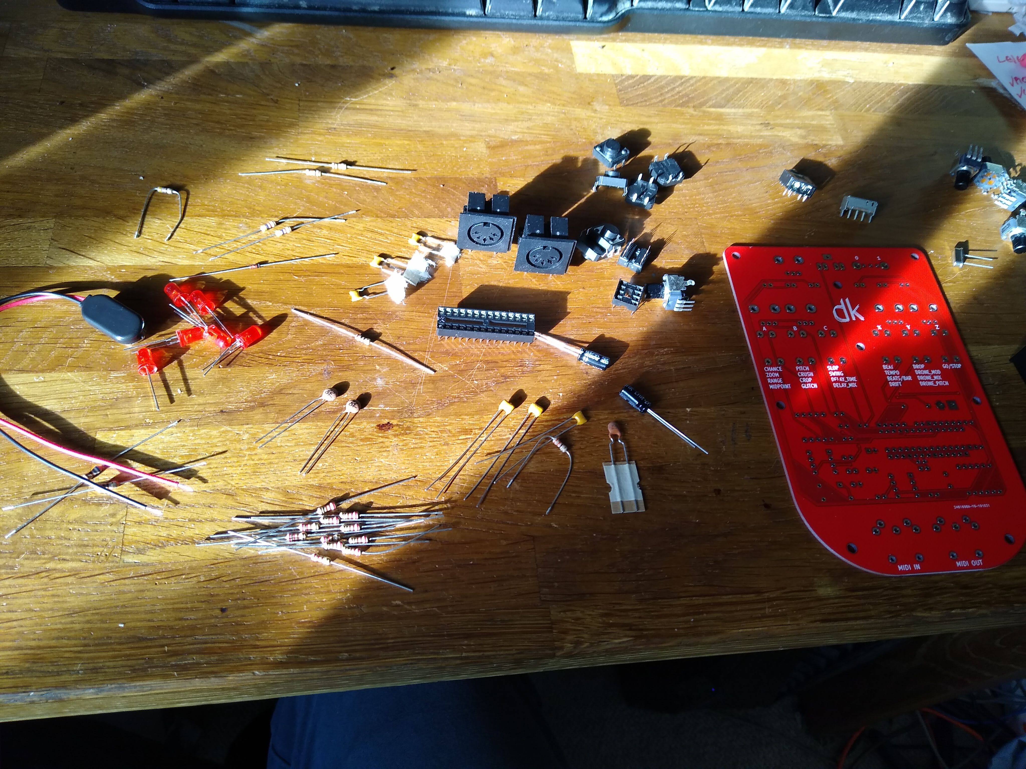
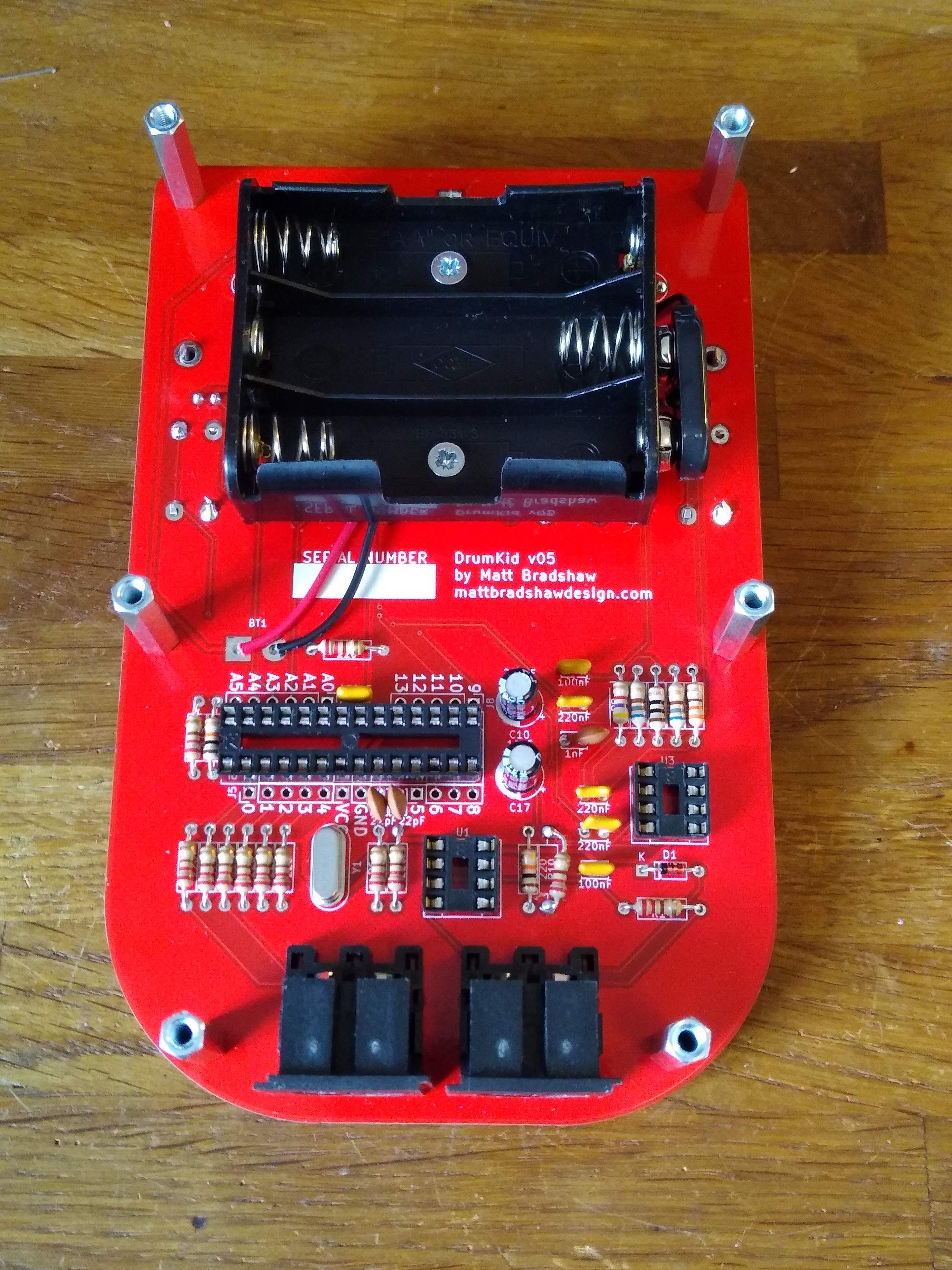
Assembly was made much easier by including the resistor and capacitor values on the silkscreen layer, which I didn't do in V4. However, I forgot to identify a few other components and polarities on the silkscreen layer. This isn't a big deal when I've got the KiCad files to refer to, but worth fixing on the next version, especially if I'm going to make DrumKid available as a kit.
The two main problems I ran into were related to two of the biggest changes I made. I significantly altered the low-pass filter on the audio output to try and remove more of the PWM carrier signal, but I'm not sure I've done it correctly - the audio sounds much brighter than I was expecting, and has some issues at full volume (possibly related to running off batteries rather than a 5V USB supply).
Another problem is that when a MIDI input is connected, each MIDI signal causes an audible click, or a loud tone, in the case of MIDI clock messages, which are sent very frequently. I had come across this issue on my breadboard prototype but assumed it was just due to the inadequate ground of the breadboard. I was wrong! I'm currently experimenting with a decoupling capacitor on the optoisolator to solve this problem.
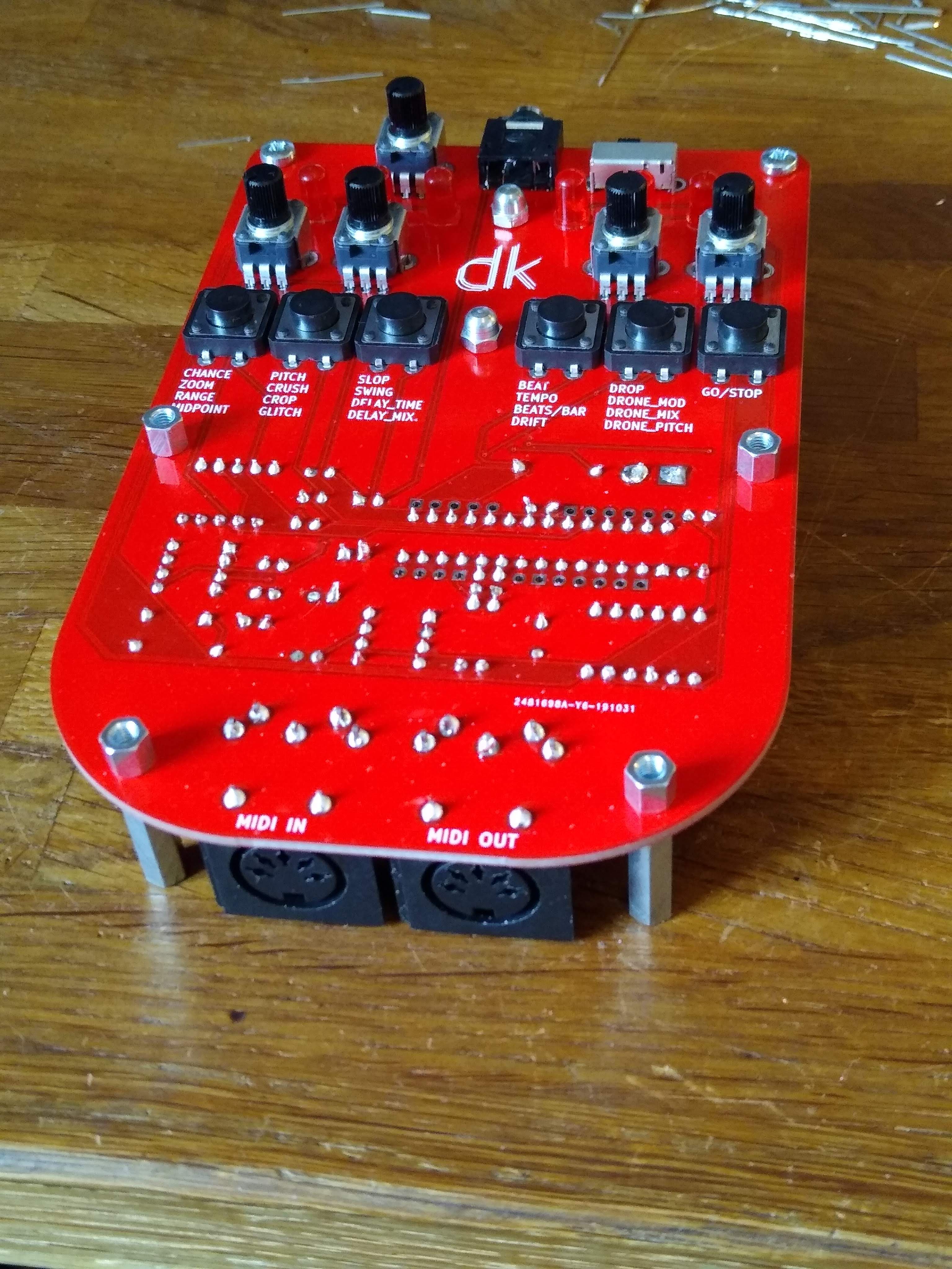
Oh, and one final, stupid mistake I made: I added a power LED so that it was obvious when DrumKid was on, but somehow managed to connect both legs of the LED to ground in the layout. Clearly KiCad's "electrical rules check" doesn't check for that...
So, overall, a bit of a mixture of good and bad, but that was probably to be expected for a fairly major revision of the design. It's certainly going to delay the release (I've tried to remove mentions of a November release date from the web where possible!). I'll see what I can do to fix the issues by hacking this PCB, then design and order a minor revision ASAP.
I always knew that this project would be a learning process. I was attempting to jump from having minimal PCB design skills to releasing a reasonably complex product with a mixture of analogue and digital circuitry, so although I did initially get a bit cross at V5 for not being perfect, I'm philosophical about it - we're getting there!
Discussions
Become a Hackaday.io Member
Create an account to leave a comment. Already have an account? Log In.
OK, I'm just a beginner. I'm looking forward to your solution to MIDI problem
Are you sure? yes | no
Sounds like you're beyond a beginner :) I'm hoping to work on the problems over the next couple of weeks, and I'll add updates here and on GitHub
Are you sure? yes | no
why R17 is a 220Ω ?which led is wrong ?
Are you sure? yes | no
it was supposed to be the resistor for the power LED, on the far right of the front (far left on the back), but i made a mistake
Are you sure? yes | no
I mean R17 seems to be 470 Ω, and in your picture, you seem to use 220 Ω. As for LED error, my understanding is that both positive and negative poles are linked to GND and I have measured PCB. There is no such problem. It seems that I have misunderstood your meaning. I'm sorry English is not my native language. Can you explain to me what's wrong with LED
Are you sure? yes | no
Oops, I just realised you're right, R17 should be 470 ohms! I'm not sure what you mean about the LED (D7), though - I can't get it to work on my board, and I think this is because I added it to the wrong place in the schematic and therefore it isn't connected properly on the PCB.
Are you sure? yes | no
I checked the schematic diagram. It seems that the lead between C4 and R19 is short circuited with LED, which makes the LED unable to work. Can I cut it off on the circuit board to make the LED work?
Are you sure? yes | no
There is no need to damage the PCB, only the grounding pins of R19 and C4 need not be welded, and then the original parts are connected by flywires
Are you sure? yes | no
Yes I think you're right, you can get the LED working with a flywire. This still leaves the problem of MIDI input not working properly and a possible problem with the filter, though!
Are you sure? yes | no