 Matt Bradshaw
I already put quite a bit of effort into developing the DrumKid concept while it was just a web app, and got it to a state that I'm pretty happy with. Once you've got the hang of playing it, it's a fun, interesting device that can be controlled even while playing another instrument. This meant that the development process for the Arduino DrumKid was mainly about the practicalities of transferring a screen-based web app, running on a powerful computer, to an Arduino with some buttons and knobs.
I quite quickly settled on Mozzi as my Arduino audio library of choice, because I've used it before and was impressed with it. It's relatively lo-fi, but then the original DrumKid happened to produce lo-fi sounding beats anyway, so that's fine.
I drew up a list of initial specifications for the device that looked something like this:
- Should be cheap to build
- Should be small and portable
- Should run off batteries
- Should be easy to play
- Should look cool
Once I'd got a basic drum beat playing on an Arduino Uno, with a few simple effects controlled in real time, I knew that the software side of the project was viable, and decided to put my effort into hardware design instead.
I made a homebrew Arduino Uno on a breadboard, knowing that this would be the basis of the final PCB. This is simpler than it sounds - you just yoink the big chip out of an Uno, put it on a breadboard, add a crystal and a couple of capacitors and hook up 5V and ground. Doing this takes the cost of the "Arduino" part of the project down to about £4.
Next I added buttons, potentiometers, and headphone socket. I tested the circuit with a 5V power supply, and it worked! But then I started thinking about battery power, which was something of a rabbit hole. The breadboard Arduino needs a fairly precise 5V power source. The simple, cheap option would be a linear regulator, but these waste a lot of energy and require 7V or more to work properly. This would mean I could either power DrumKid with a 9V battery (which would be dead very quickly) or 6 AA/AAA batteries, which is a silly number of batteries for such a simple device.
I was looking for a voltage regulator chip which was cheap, efficient, easy to solder (i.e. through-hole), and which wouldn't require too many batteries. Eventually, I stumbled onto the MAX756 chip, a step-up chip which could happily output 5V from two AAA batteries. It cost £4, which is about ten times more than a linear regulator, but the rest of the project was working out pretty cheap so I decided it was worth it.
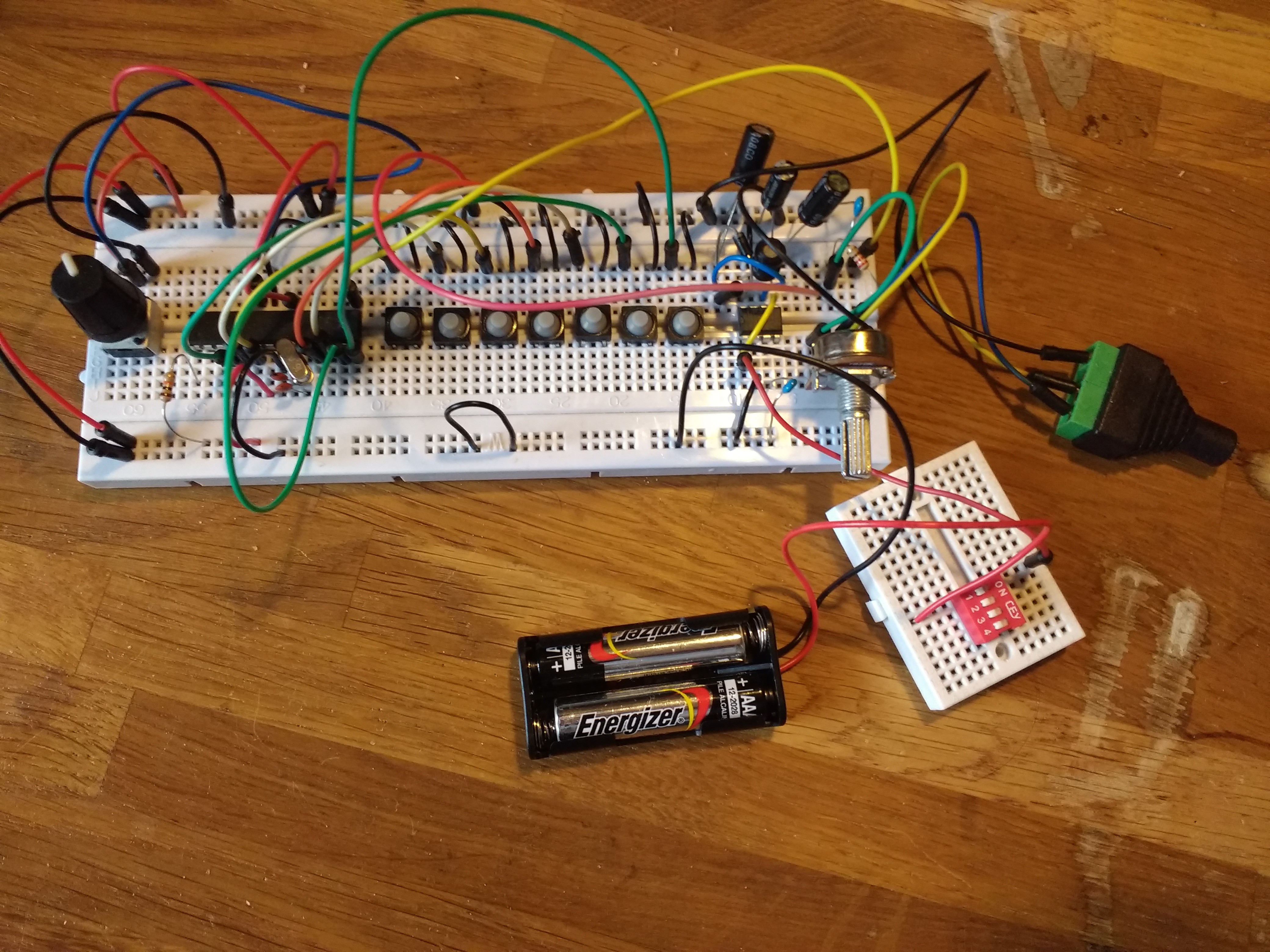
After a frustrating few hours of misunderstanding the MAX756's datasheet, I finally got a stable 5V out of it. I hooked it up to the rest of the DrumKid test circuit on the breadboard, and had a moment of simultaneous excitement and frustration. On the one hand, I was successfully running DrumKid from two AAA batteries, using only about £10 of components in total. On the other hand, there was a weird, high, badly-tuned-radio noise that hadn't been present when I used a "proper" 5V power supply.
At this point, perhaps stupidly, my optimism took over. While trying to get the MAX756 to work, I had found several people mentioning that it was very sensitive and wouldn't work properly on a breadboard. Someone who attempted a breadboard circuit with a MAX756 was derided on Stack Exchange for his "long loops of jumper wire", which were not only present in my circuit, but which caused the weird noise to change when I touched them. I decided that, in the absence of a more sensible plan, I would push on and design the PCB, in the hope that when I added the components, the noise would be magically gone. And that's where I've got to so far...
Next up: PCB design, ordering/testing the PCB, and (if all goes well) designing a case.
Discussions
Become a Hackaday.io Member
Create an account to leave a comment. Already have an account? Log In.