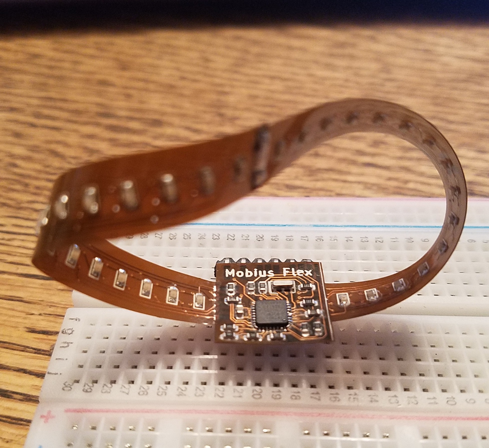
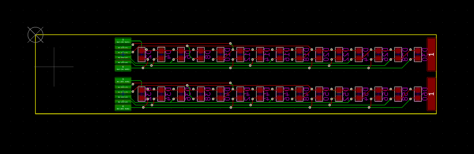
Close
0%
0%

Möbius Flex

My entry for the flex PCB contest. I'm not sure how well a flex PCB will work for an LED-studded möbius strip, but let's find out.

Similar projects worth following
Möbius flex is a single-sided ;) flexible PCB (made from double-sided parts) with an Atmega 328p microcontroller and 60x 0603 LEDs designed for the Hackaday Flex PCB contest. It fits within a 13 sq cm total board area, so it can be manufactured using the contest's free PCBs to the best 60 entries. I couldn't wait, so I ordered a set of three from OshPark on my own dime, and this is the result.

View all 8 components

  • Laser Cut Stencil and Assembly

    Chris Miller04/09/2019 at 18:18 0 comments

    The boards arrived yesterday and I was anxious to get one assembled and tested.  I headed over to Bozeman Makerspace where I have my office and access to the reflow oven.

    I was able to create a useable solder paste stencil using our K40 laser cutter and some mylar transparency film I had laying around.  After much experimentation, I found that I was able to cut acceptable stencils with a few tricks.  The mylar melts a bit around the edges and makes larger holes than anticipated.  And it's a very fine line between melting and not cutting through.  So to gain some additional control over the melting, I covered the back of the mylar in painter's tape.  When peeled off, this left a clean cut on the back and minimized excessive melting around the holes.  I also specified an exaggerated beam size of 0.3mm (normally about 0.15mm).  Laser powers vary greatly, especially on the K40, but with our setup the best cuts were at 8% power and 800mm/sec with very light air assist.

    For soldering, I wanted to do the majority with the stencil and reflow oven, but because the board is double sided and very thin, I first soldered LEDs on the back side with an iron and lead free solder.  The higher melting temp allowed me to put it back in the reflow oven with leaded solder on the top side and the bottom LEDs will not melt.

    I cut the boards apart on the cut lines with a sharp knife before stenciling.  To support the boards with components already on the back side, I created a channel between two scrap PCBs that the LEDs would sit in.  I then taped down the flex and stencil with painter's tape.  The stencil should hinge on the tape to allow removal without smudging the solder paste.

    Pasting and soldering was straight forward.  I do most of my hand assembly with 0805 components, and this uses 0603, so it was a bit more of a challenge.  But overall it went very well.  The 328p IC had one visible bridge after reflow, which I was able to clear with a flux pen and a single swipe of the iron.

    I then joined the two strips end-to-end by making two small cuts in each, so they interlock with copper to copper fingers.  I used a straight edge and small spring clamps to align the two halves.  Some flux and solder flowed nicely into the joint, and the interlocking fingers were soldered on both sides.

    To join the narrow strip to the central hub, I first tinned the pads on the 16mm square hub PCB.  I tinned the contacts on the strip, but removed most of that solder with flux and solder wick.  Then I aligned the overlapping contacts with the aid of a straight edge and small spring clips so that some of the solder on the hub board is exposed.  A touch of the iron on each one reflowed the solder and joined it to the strip.  Once a few pins are tacked in place, more solder can be carefully added to create a strong joint.  Once soldered, the flex PCB allows a visual inspection for shorts using a bright light source.

    The second strip connection was a bit more tricky.  Because of the twist in the strip, I had to find a block of wood to prop up the central hub and not crease the strip.  And the spring clamps did not work in this configuration so I had to hold both parts with one hand while soldering with the other.

    The 6 pin power and programming header is then soldered on by first tinning one pin and reflowing with the iron.  Then heat and solder is applied to each of the 5 remaining pins until it flows onto the copper pad.

    This board does not have a USB interface, so it must be flashed using an ISP programmer like the AVRISP, AVR Dragon, etc...  I chose to use another arduino because I had it laying around.

    I wrote up a quick blink sketch, flashed, and it worked first try!

    Next post will be about the simple...

    Read more »

  • Paper Mockup - PCBs on Monday

    Chris Miller04/05/2019 at 19:44 0 comments

    I received the shipping notification from OshPark.  Should have real flex PCBs by Monday.  Meanwhile here's a scale mockup cut from bristol paper.  I think the flex is going to bend a little more evenly, but we'll see once it has LEDs soldered to it.

    Bristol paper prototype with Neopixel for scale

  • Flex PCBs and Components Ordered

    Chris Miller03/29/2019 at 22:38 0 comments

    I've ordered the flex PCBs from OshPark and the components from Digikey.  I should have them within a few weeks.  Next update will likely be assembling one.  I have not ordered an SMD stencil yet.  Since the flex takes a little longer to arrive, I thought I'd spend the next week or two experimenting more with laser cutting or vinyl cutting a stencil from Kapton or mylar.  I've had some success in the past, but these are small parts..

  • Routing the MCU

    Chris Miller03/25/2019 at 22:39 0 comments

    I had already decided to use the VQFN version of the Atmega328p on this design. That gives me plenty of IOs and a simple way to program it through 6 pins.  I can also power the programmed device through the programming header's 5v and gnd pins.

    Initially I thought the layout would be on both sides of the central hub.  I was looking at multiple resistor packs, smaller components, both sides, etc...  But it turns out that using 0603 passives, I was able to get the MCU, its supporting components, and 12 current limiting resistors on the top side of the 16x16mm main PCB.  I used the smallest 6mil tracks and spacing that OshPark supports for flex PCBs.  This allowed me to put all of the board interconnects and the programming header on the bottom for a clean look.

    Central hub layout

  • Designing the Charlieplex

    Chris Miller03/25/2019 at 22:29 0 comments

    I've never officially used charlieplexing before, so I wanted to find a good guide on creating the schematic.  I followed the great example at https://stkwans.blogspot.com/2012/05/designing-large-charlieplex.html

    I decided that 60 LEDs total would result in a good spacing for the size available.  I am betting that some empty space between the LEDs will let the flex PCB twist evenly along the 120mm or so of strip.

    The easiest way to lay out two double-sided strips of 30 LEDs was to create two arrays that each use 6 microcontroller pins.  That way they both have the same connection footprint, and it gives some symmetry to the design.  Half of the LEDs (even/odd) are on the back of the PCB.

    I designed one half of the schematic in KiCad first, and once I confirmed that I could route it, I copy/pasted the schematic section and replicated the routing by hand.

  • Designing the Physical Connections

    Chris Miller03/24/2019 at 02:54 0 comments

    With the three part layout somewhat decided, I needed to start thinking about how the three parts are connected together.  I figured I would need to create some custom footprints to fit the available space, so I started with these.

    I knew that with charlieplexed arrays of LEDs, it would not matter which pins were connected to what on the MCU, so I created a simple single-sided footprint for 6 pins that would allow me to control 30 LEDs per arm.  I designed these to have enough length to be easy to join, and just enough width to fill the available 8mm.  This footprint can be soldered to another mirrored footprint by tinning one side, then overlapping them partially so the tinned pads are still exposed.  Then run a soldering iron across the tinned pads.  They should melt into the opposite footprint and create a connection.  I've used this technique before making breakout boards for cheap LCD displays.  It's similar to how NeoPixel strips are joined.

    The ends of the two LED arms would be joined with a similar single pad.  Since I'm adding a twist in the boards, I created this footprint to have pads on both sides of the PCB.

    I also created a 0.1in spacing, 6 pin ICSP connector that would allow programming and power.  I plan to solder some 90 degree headers to this, so it's breadboard friendly.

  • Determining the form factor

    Chris Miller03/24/2019 at 02:24 0 comments

    I really wanted to stay within the 2 sq in, or 13 sq cm constraint.  Not just for cost, but for the challenge.  I want the experience of laying out a dense circuit in Kicad.

    Initially I assumed I could do a central hub with long arms sticking out that would be joined with solder once the components are installed.  When measuring just the solid area of my designs, I could create a much larger mobius strip.  It turns out that OshPark (and I suspect most vendors) measure your design by it's bounding box, or the smallest rectangle it will fit into.

    With this in mind I investigated layouts that could be cut apart, then re-assembled in a different configuration.  I started looking at the minimum area needed for a central hub containing the microcontroller.  Measuring an Atmega 328p QFP I had on hand, I found that this chip has a 12mm x 12mm footprint.  This seemed rather large compared to 2 sq inches, so I decided to use the lead-less VQFN version of the chip.  It measures only 5x5mm, which allowed me to fit my central hub including current limiting resistors and interconnects into 16mm x 16mm.  At this point I also decided to use 0603 components instead of my go-to and easy-to-place 0805s.

    Placing this at one end of a 16mm x 81.25mm rectangle leaves enough material for two additional strips, 8mm x 65.25mm.  These strips will contain the LEDs on both sides, and will be soldered together, and to the hub, with the mobius twist.

View all 7 project logs

Enjoy this project?

Share

Discussions

Elliot Williams wrote 01/31/2020 at 08:40 point

Stumbled on this just now.  Very cool idea.

  Are you sure? yes | no

Szabolcs Lőrincz wrote 04/29/2019 at 21:33 point

weird flex but ok

  Are you sure? yes | no

deʃhipu wrote 04/09/2019 at 14:37 point

It's Möbius.

  Are you sure? yes | no

Chris Miller wrote 04/09/2019 at 15:29 point

Fixed.  Feel better?

  Are you sure? yes | no

deʃhipu wrote 04/09/2019 at 15:39 point

Infinitely, thank you!

  Are you sure? yes | no

Clara Hobbs wrote 04/29/2019 at 22:49 point

Not enough mëtäl.  How about Möbïüs?

  Are you sure? yes | no

Ted Yapo wrote 04/09/2019 at 12:47 point

So it's a single-sided flex PCB then?

Very cool!

  Are you sure? yes | no

Chris Miller wrote 04/10/2019 at 05:24 point

Yes!  Thanks for pointing that out!  I updated the description.

  Are you sure? yes | no

Similar Projects

Does this project spark your interest?

Become a member to follow this project and never miss any updates