 Chris Miller
With the three part layout somewhat decided, I needed to start thinking about how the three parts are connected together. I figured I would need to create some custom footprints to fit the available space, so I started with these.
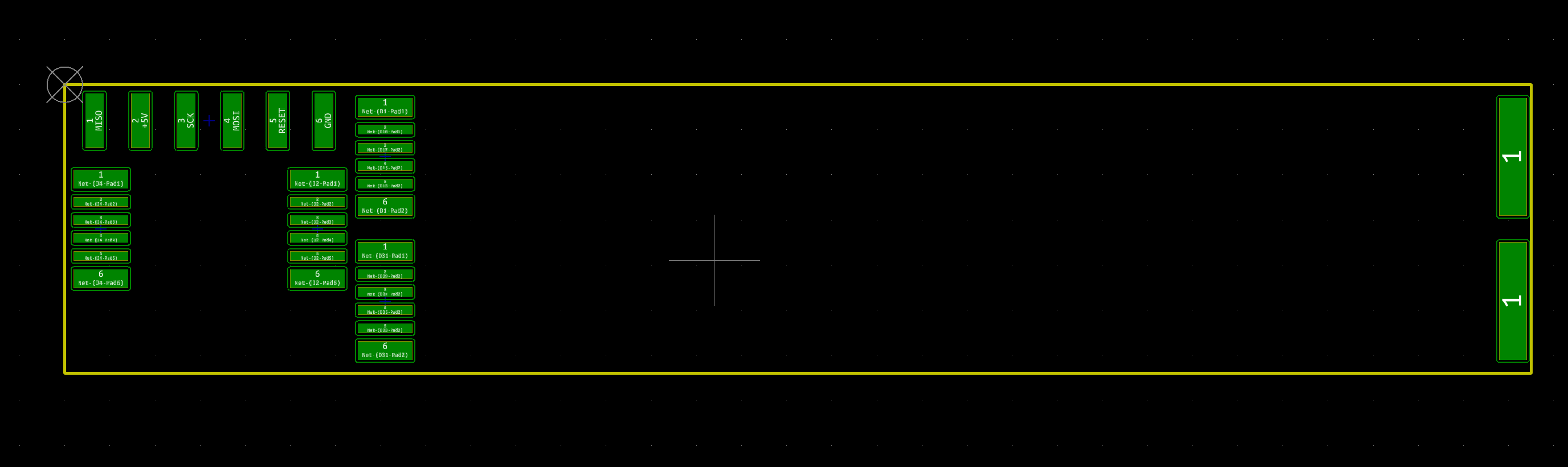
I knew that with charlieplexed arrays of LEDs, it would not matter which pins were connected to what on the MCU, so I created a simple single-sided footprint for 6 pins that would allow me to control 30 LEDs per arm. I designed these to have enough length to be easy to join, and just enough width to fill the available 8mm. This footprint can be soldered to another mirrored footprint by tinning one side, then overlapping them partially so the tinned pads are still exposed. Then run a soldering iron across the tinned pads. They should melt into the opposite footprint and create a connection. I've used this technique before making breakout boards for cheap LCD displays. It's similar to how NeoPixel strips are joined.
The ends of the two LED arms would be joined with a similar single pad. Since I'm adding a twist in the boards, I created this footprint to have pads on both sides of the PCB.
I also created a 0.1in spacing, 6 pin ICSP connector that would allow programming and power. I plan to solder some 90 degree headers to this, so it's breadboard friendly.
Discussions
Become a Hackaday.io Member
Create an account to leave a comment. Already have an account? Log In.