 Chris Miller
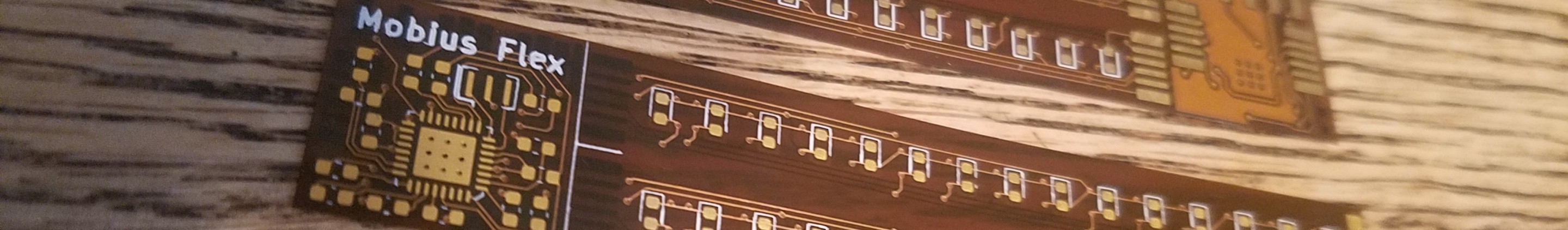
The boards arrived yesterday and I was anxious to get one assembled and tested. I headed over to Bozeman Makerspace where I have my office and access to the reflow oven.
I was able to create a useable solder paste stencil using our K40 laser cutter and some mylar transparency film I had laying around. After much experimentation, I found that I was able to cut acceptable stencils with a few tricks. The mylar melts a bit around the edges and makes larger holes than anticipated. And it's a very fine line between melting and not cutting through. So to gain some additional control over the melting, I covered the back of the mylar in painter's tape. When peeled off, this left a clean cut on the back and minimized excessive melting around the holes. I also specified an exaggerated beam size of 0.3mm (normally about 0.15mm). Laser powers vary greatly, especially on the K40, but with our setup the best cuts were at 8% power and 800mm/sec with very light air assist.
For soldering, I wanted to do the majority with the stencil and reflow oven, but because the board is double sided and very thin, I first soldered LEDs on the back side with an iron and lead free solder. The higher melting temp allowed me to put it back in the reflow oven with leaded solder on the top side and the bottom LEDs will not melt.
I cut the boards apart on the cut lines with a sharp knife before stenciling. To support the boards with components already on the back side, I created a channel between two scrap PCBs that the LEDs would sit in. I then taped down the flex and stencil with painter's tape. The stencil should hinge on the tape to allow removal without smudging the solder paste.
Pasting and soldering was straight forward. I do most of my hand assembly with 0805 components, and this uses 0603, so it was a bit more of a challenge. But overall it went very well. The 328p IC had one visible bridge after reflow, which I was able to clear with a flux pen and a single swipe of the iron.

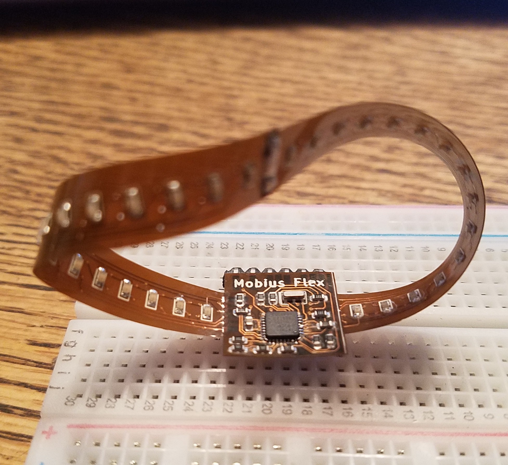
I then joined the two strips end-to-end by making two small cuts in each, so they interlock with copper to copper fingers. I used a straight edge and small spring clamps to align the two halves. Some flux and solder flowed nicely into the joint, and the interlocking fingers were soldered on both sides.

To join the narrow strip to the central hub, I first tinned the pads on the 16mm square hub PCB. I tinned the contacts on the strip, but removed most of that solder with flux and solder wick. Then I aligned the overlapping contacts with the aid of a straight edge and small spring clips so that some of the solder on the hub board is exposed. A touch of the iron on each one reflowed the solder and joined it to the strip. Once a few pins are tacked in place, more solder can be carefully added to create a strong joint. Once soldered, the flex PCB allows a visual inspection for shorts using a bright light source.
The second strip connection was a bit more tricky. Because of the twist in the strip, I had to find a block of wood to prop up the central hub and not crease the strip. And the spring clamps did not work in this configuration so I had to hold both parts with one hand while soldering with the other.
The 6 pin power and programming header is then soldered on by first tinning one pin and reflowing with the iron. Then heat and solder is applied to each of the 5 remaining pins until it flows onto the copper pad.
This board does not have a USB interface, so it must be flashed using an ISP programmer like the AVRISP, AVR Dragon, etc... I chose to use another arduino because I had it laying around.
I wrote up a quick blink sketch, flashed, and it worked first try!
Next post will be about the simple demo firmware. Stay tuned...
Discussions
Become a Hackaday.io Member
Create an account to leave a comment. Already have an account? Log In.