 Arkadi
Stage 1: PCB Design

There are many development boards out there based on the Atmega328P / arduino compatible. And many of them are probably low power compatible / oriented. Regardless I have decided to make my own design. Just to see what will come out of it.
So first of all, I will start by saying that perhaps the Atmega328P isn't the most low power microcontroller out there, and many of the newer arm based MCU`s are much more powerful while have much lower power consumption. But if you want to start designing boards, start with the Atmega328P :) and making it arduino compatible will bring some people at least to try it out and tinker with it.
The main components for the design: atmega328p dip package, battery charger, voltage regulator. And headers for an nrf24l01 module. With some prototyping area which is very handy to have for stand alone projects. See schematics
Schematics:

Note: The atmega328 base schematics (Crystal / Capacitors) is based on sparkfun design.
Components:
Main components:
PCB - https://github.com/arkadiraf/Arduino_LowPower/tree/master/Circuit
ATmega328P - DIP package
MCP73831 - LI-ION Battery charger http://www.microchip.com/wwwproducts/en/en024903
TLV733P - 3V3 LDO Regulator http://www.ti.com/lit/ds/symlink/tlv733p.pdf
NRF24L01 - Transceiver http://www.seeedstudio.com/document/pdf/DS_nRF24L01.pdf
Some Capacitors , Resistors all 0805, see schematics.
8 MHz Crystal, DIP package. 20pf.
JST 2.0 - Connectors for lithium battery and solar panel.
Component choosing reasoning:
I chose the atmega328 in its DIP package so I will have access to all the pins without the need to add breakout headers to the pins of the SMD version. Making the design simpler, in addition the DIP package can be removed and flashed (for the arduino bootloader) using an arduino uno development board (DIP version) allowing me not to add the icsp headers to flash the MCU on board.
NRF24L01 Transceiver is very popular, and cheap so I use it extensively in my projects.
The rest of the components are just what I had already from previous projects.
The MCP73831 is a very common lithium charger IC, and sparkfun has different designs with it, so it was a good reference.
The TLV733P regulator fitted my requirements as it has an enable option with typical 0.1ua when disabled. In addition it has very low dropout voltage, up to 125mv for full 300ma.
Configurations:
The main configuration is in choosing how you want to power up the board. In my design the MCU supply voltage (VCC) is configured through a jumper. While you have the option to power it directly from the battery (Vbat), or using the 3v3 voltage regulator output (3V3). In addition you can set the jumper between Vin and Vcc, for battery charging through the arduino ftdi header.
The most low power configuration is to power the MCU directly from the battery. In this scenario you can disable all peripherals including the NRF24 module through the voltage regulator enable pin. Achieving up to a few microamps current. Based on this article from sparkfun https://www.sparkfun.com/tutorials/309 .
The alternative is to set the MCU power supply from the voltage regulator, which isn't the best for low power but good enough, at typical 34 microamps for the regulator (based on the datasheet). For this option you need to leave the pull down resistor unpopulated and add a pull up resistor to Vin.
Alternative option is to keep the pull down resistor adding a pull up resistor to Vin. it will use up some power but will make an interesting combination at which the circuit will automatically be enabled when charging is occurred. For example when using a solar panel to charge the battery, when the battery is running low. The MCU can pull down the enable pin disabling itself and all surrounding circuit. Running practically on zero consumption (or the 0.1 microamps, specified in the datasheet for the regulator). When the sun is up again. The solar panel pulls the pin high starting charging and enabling back the circuit.
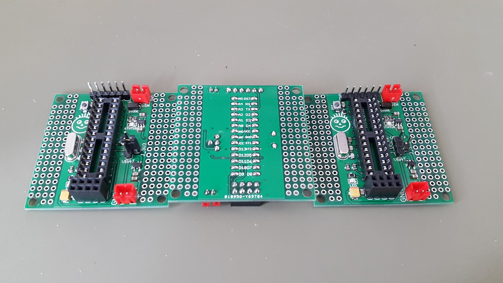
Assembly:
For this project I used a syringe to place the solder paste on the pads, after which manually placing the component. It didn't turn out as clean as using a stencil.

After the reflow oven the results are much better, but some fixes where required as seen in the close up image.


And hand soldering the DIP components:
Going further:
So now that the board is assembled and tested for basic functionality the actual low power tinkering is required. For this I am planning to acquire some measurement instrument. Considering my current budget. I am planning for something such as the µCurrent. And see how I can implement thouse tricks explained in the sparkfun article. After that… probably some outdoor sensing device. As I want to test this combination with auto power up with the rising sun :)

Resources:
GitHub: https://github.com/arkadiraf/Arduino_LowPower
Atmega328 Low power settings: https://www.sparkfun.com/tutorials/309
Discussions
Become a Hackaday.io Member
Create an account to leave a comment. Already have an account? Log In.
First thoughts on the project: since you want to safe power, you want to get rid of the LEDs and -this one is a personal preference- but I would add all the footprints of the Atmega328P onto the board, this makes it more versatile.
I remember seeing a video of Dave Jones on the EEV blog talking about speeds of MCUs vs. work time vs. power consumption and it made me wonder if the Atmega could be controlling a PSUs voltage output (PWM of a boost/buck) and an oscillator depending (VCO) on needs - totally over the top and unnecessary but a cool topic.
Are you sure? yes | no
I only added two LEDs, one for charging status connected to the MCP73831 output, and the other one is connected to the MCU and is good for initial testings. regarding the footprint, I chose a DIP version footprint so that you have access to all the pins if necessary with silk screen on the button of each pin so that it will be easier to wire the additional circuit.
Are you sure? yes | no
ahh, they aren't connected to the solder pads in the first row. I see. sorry and I thought the LED was a power indicator ;)
Are you sure? yes | no