 blinkingthing
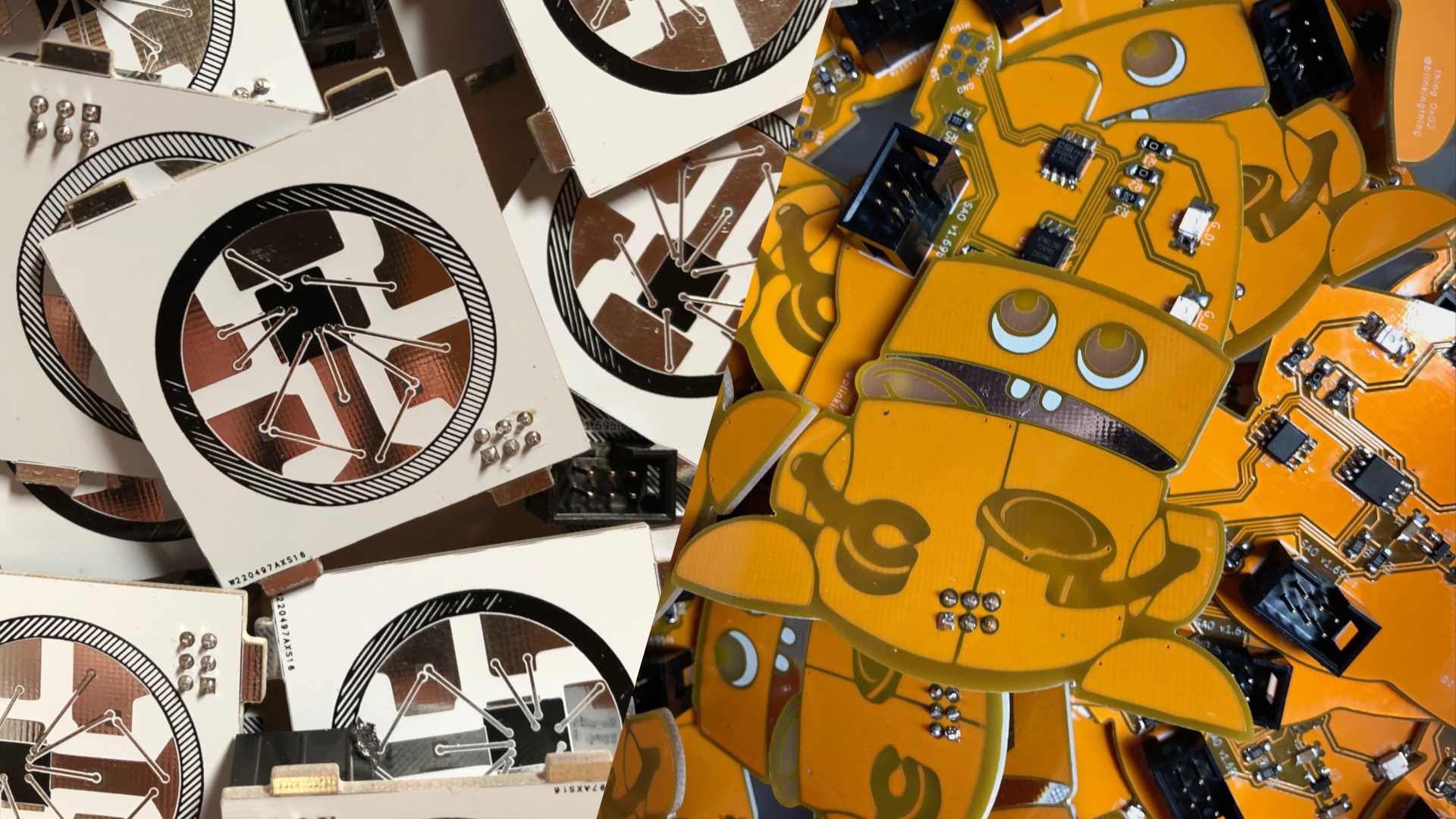
Assembly
I've been assembling Shitty Pixel and Robot Bank SAOs all weekend. I don't think I've mentioned it yet but I was simultaneously working on a few different SAO designs. I could only decide on two, so I'm using the same circuit from the Shitty Pixel for a second SAO, the Robot Bank.
I went through a few different trial order of operations trying to figure out the most efficient way to assemble the boards and then test, troubleshoot and fix the ones with issues. This is how I ended up doing it.
I lined up as many PCBs as would fit on my anti-static mat.
Then I tinned at least one pad per component I would be placing.
Then I tack soldered one side of all the components I could comfortable place with the current orientation of my workspace. Once I completed everything I could from that position, I rotated the anti static mat 90º and placed the components that were in that orientation. After repeating this process two more times, soldering all pads along the way after components had been placed, I moved on to programming the boards.
This is where the ability to program the ATtiny in circuit was really valuable. I focused mainly on getting the hardware finished knowing that I could figure out the software at a later date. Now with the hardware in hand, I finished the last few bits of code and started uploading the code using the Arduino IDE and a Sparkfun Tiny AVR Programmer and Pogo ISP adapter kit.
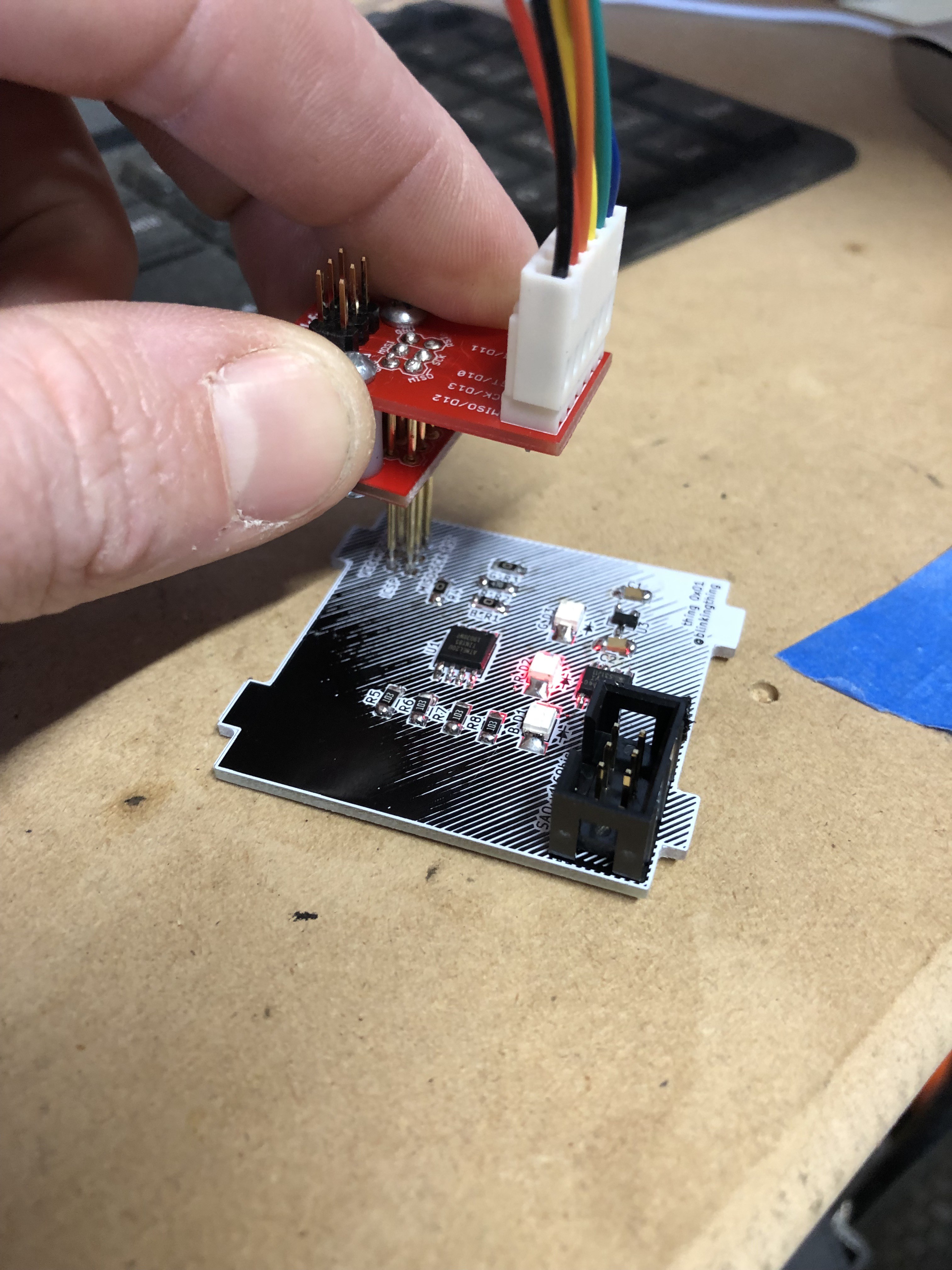
This took a few mouse clicks and seconds of waiting per PCB burning the bootloader and programming the ATtiny with the arduino sketch. When the sketch is done being loaded, it automatically starts running and I could quickly see if it was running properly and I could check to see if all three LEDs were working.
The next step on the assembly line is QC. Here I used the SAO Dev Board atop a raspberry pi to check the following:
- Does it power up through the SAO connector
- Check I2C bus for expected devices at expected addresses.
- Check I2C control of LEDs by activating modes other than default mode.
- Flash EEPROM with desired data using python script. Read back and verify EEPROM data.
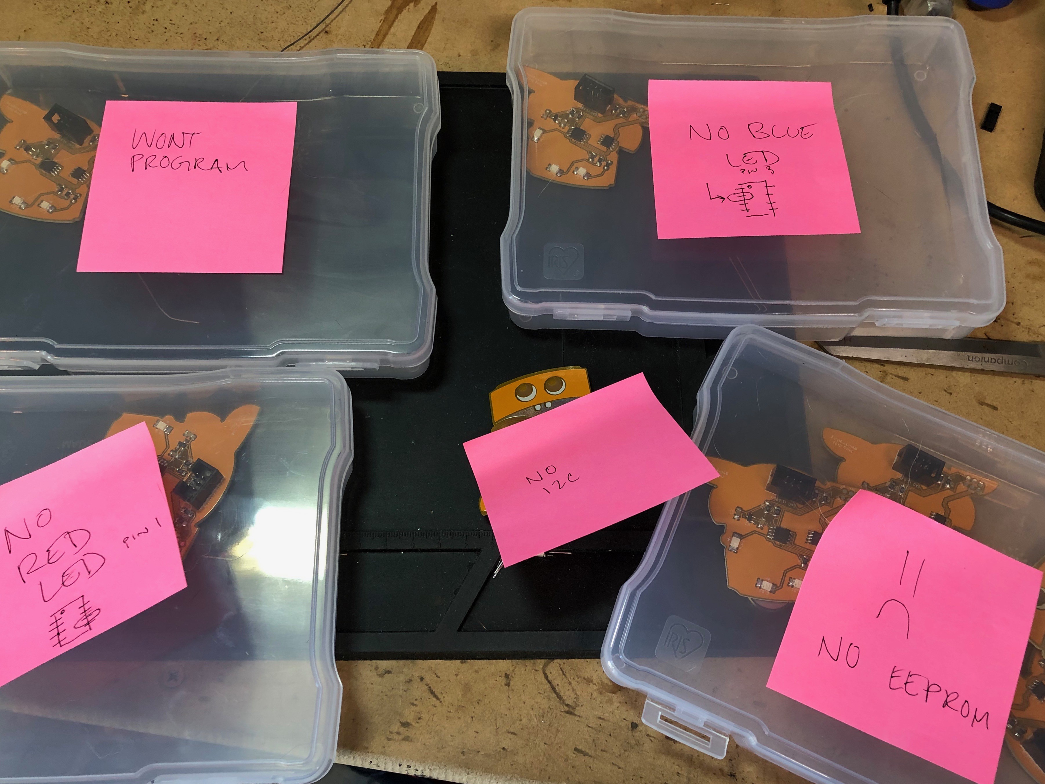
If any of the boards failed any test, I separated them into different piles with similar problems so I could keep working through the pile of boards to be tested and I could troubleshoot later. I ended up using post its with notes, including tiny pin-out diagrams as cheat sheets for common problems that kept coming up. By far, the most common issue was the EEPROM chip not being detected on the bus and the second most common problem was not being able to program the ATtiny. Both these problems were caused by soldering errors by me. Hand soldering these small parts by hand with my naked eye has been a challenge. I do have a microscope that I've been using to get a better look at the troublesome areas, this is an extremely useful tool but slows me down a bit. So, I've been soldering the majority of the boards without magnification, only using it when I have issues.
After each PCB passes all my quality checks, I seal them up in the final packaging.
Packaging
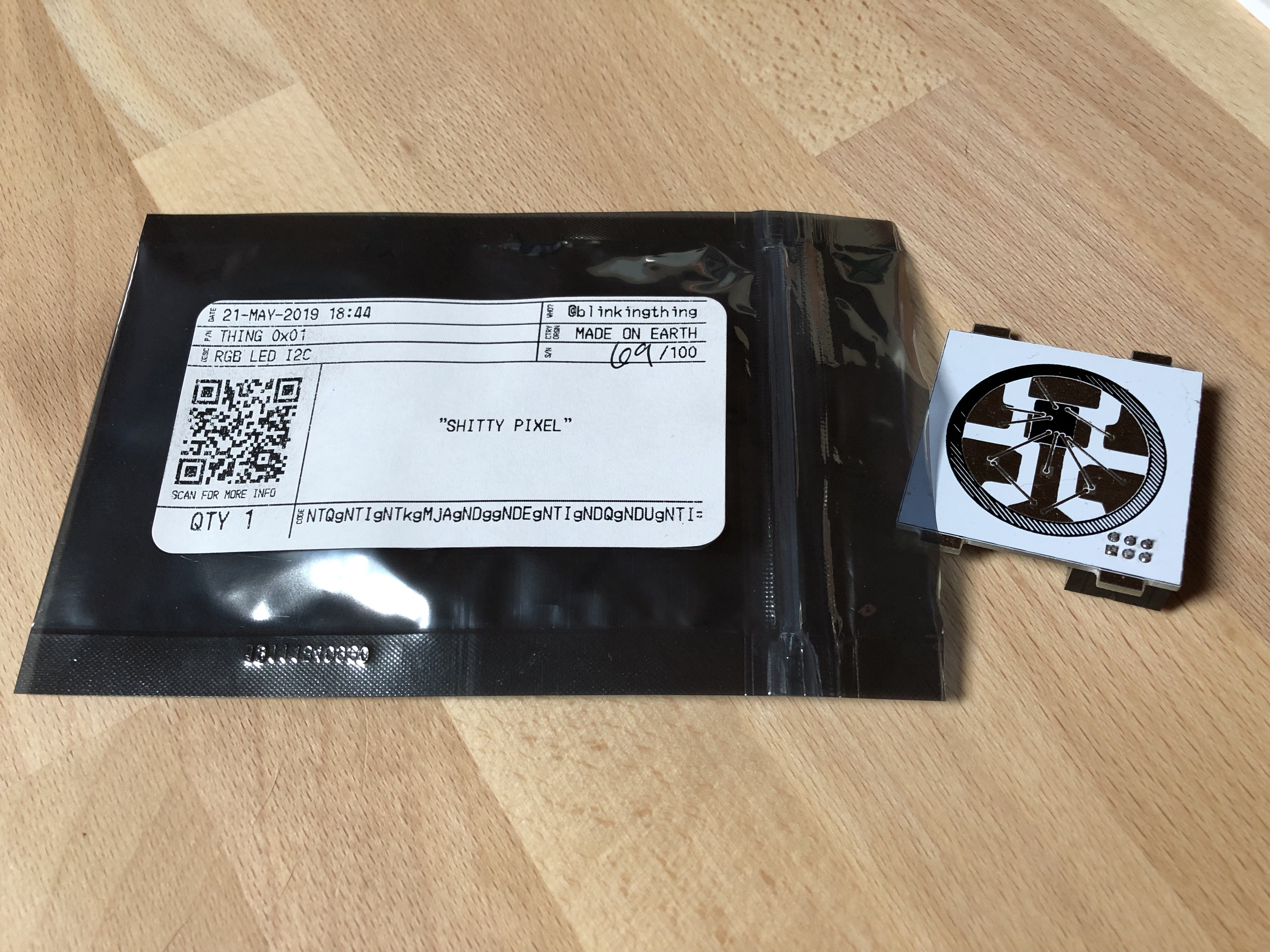
I wanted to do something slightly more than just putting these SAOs in an anti-static bag so I designed some labels with a cipher and a QR code that links to a digital datasheet that I also designed. I basically wanted it to look like the labels on the envelopes all the Digikey components came in. Theres a few secrets and codes involved with my SAOs and the packaging gives you hints to find them and figure them out. I drew some inspiration from the Hack for Satan Badge from DC26 with the VHS box, I know that is completely different from what I've done, but it's nice to see attention paid to the packaging and I wanted to follow suit.
That's all for now. I have SAOs in stock now. Will add the Tindie link once they are approved for sale.
Discussions
Become a Hackaday.io Member
Create an account to leave a comment. Already have an account? Log In.