Close
0%
0%

IoT GitHub Frame

This project will help you track the popularity of the selected github repository live

Public Chat
Similar projects worth following
IoT GitHub Frame is a photo frame with built-in device based on the ESP32 module. This project will help you track the popularity of selected GitHub repository. You will be able to follow live the number of stargazers, watchers and forks. The frame can also display the number of daily stargazers. Simple configuration, automatic updates via HTTPS OTA, stability of operation. These are just some of the advantages of this project. The frame will look great on the wall in your home or office.

Check out the GitHub page for more details.

  • 1 × ESP-32 WROOM DevKit 1.0
  • 1 × 4-digit display TM1637 0.56" - white color
  • 1 × Pin Header Right Angle Male
  • 1 × LED Diode 5mm RGB with common anode
  • 3 × LED Diode 3mm white

View all 20 components

  • 1
    STEP 1.
    What you will need
    1. ESP-32 WROOM DevKit 1.0 – 1 pc.
    2. 4-digit display TM1637 0.56" - white color– 1 pc.
    3. 4-digit display TM1637 0.36" – 1 pc.
    4. 4 Pin F/F 200mm Cable – 4 pcs.
    5. JST 1.25 2-Pin Male - Female Connector – 2 pcs.
    6. Micro JST 1.25 2-Pin Male - Female Connector – 2 pcs.
    7. Universal PCB stripboard 50x70mm PI-01 – 1 pc.
    8. Carbon Film Resistor – 220 ohm – 5 pcs.
    9. Carbon Film Resistor – 2,2k ohm – 3 pcs.
    10. Breadboard Jumpers - 1 set
    11. Pin Header Right Angle Male – 1 pcs.
    12. LED Diode 5mm RGB with common anode – 1 pc.
    13. LED Diode 3mm white – 3 pcs.
    14. Round Push Button - momentary – 10mm – 2 pcs.
    15. ON-OFF switch – 1 pc.
    16. Cable USB A – USB micro – 1 pc.
    17. Phone charger with usb output 5V – 1 pc.
    18. Heat Shrink Tubing - 1 pc.
    19. IKEA RIBBA photo frame – 21x30cm ( it must be thick ) – 1 pc.
    20. Self-adhesive paper for the printer – 1 pc.

    Tools

    1. Soldering iron
    2. Solder
    3. Drill or screwdriver
    4. Drills: 7, 10, 13
    5. Hot glue gun
    6. Knife
    7. Printer
  • 2
    STEP 2

    Solder electronic components to the PCB as in the picture below. Soldering start from the lowest elements. For connecting displays and LEDs use angled connectors.

    After finishing soldering, your board should look similar to this one

  • 3
    STEP 3

    In the printouts folder you will find print templates that will help you drill holes:

    Print them and then tape back template to the back of the frame and side template on the right edge of the frame. Use the appropriate drills to drill the holes. Cut the holes for the displays and the button with a knife.

    Insert the displays and diodes in the holes using hot glue.

    That's how it should look from the front

View all 6 instructions

Enjoy this project?

Share

Discussions

Paweł Skórka wrote 03/28/2019 at 15:53 point

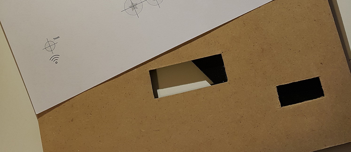
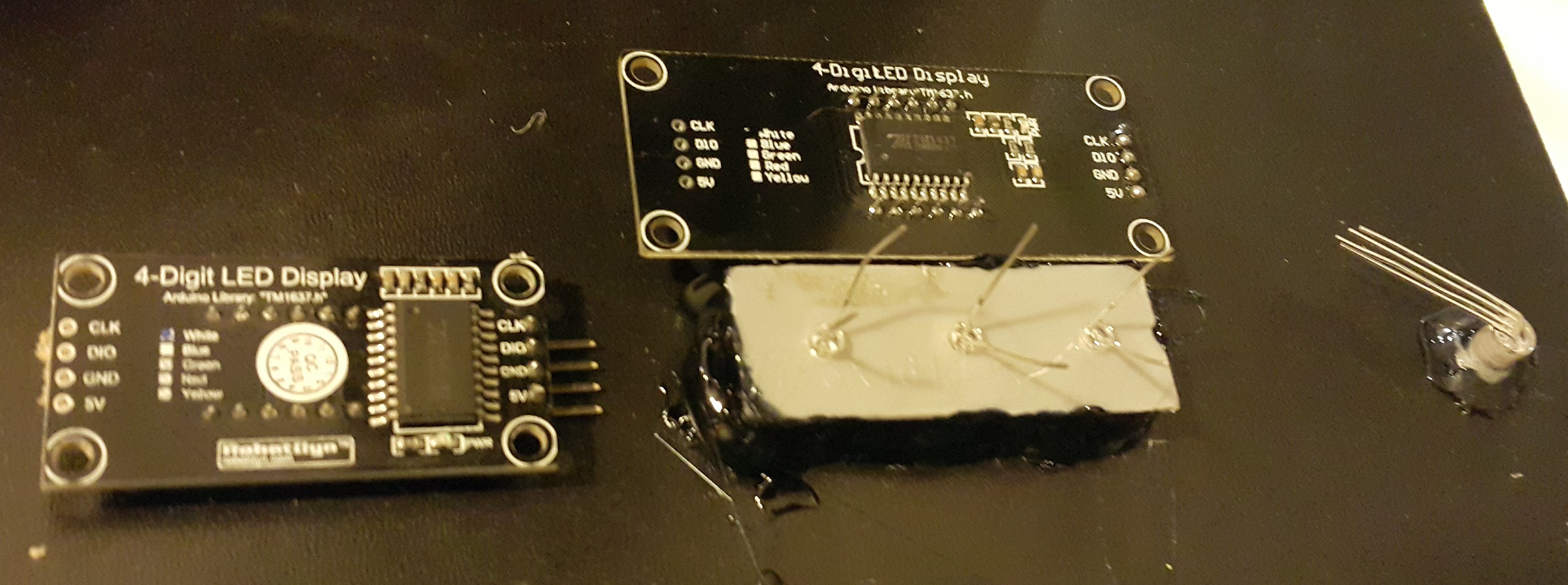
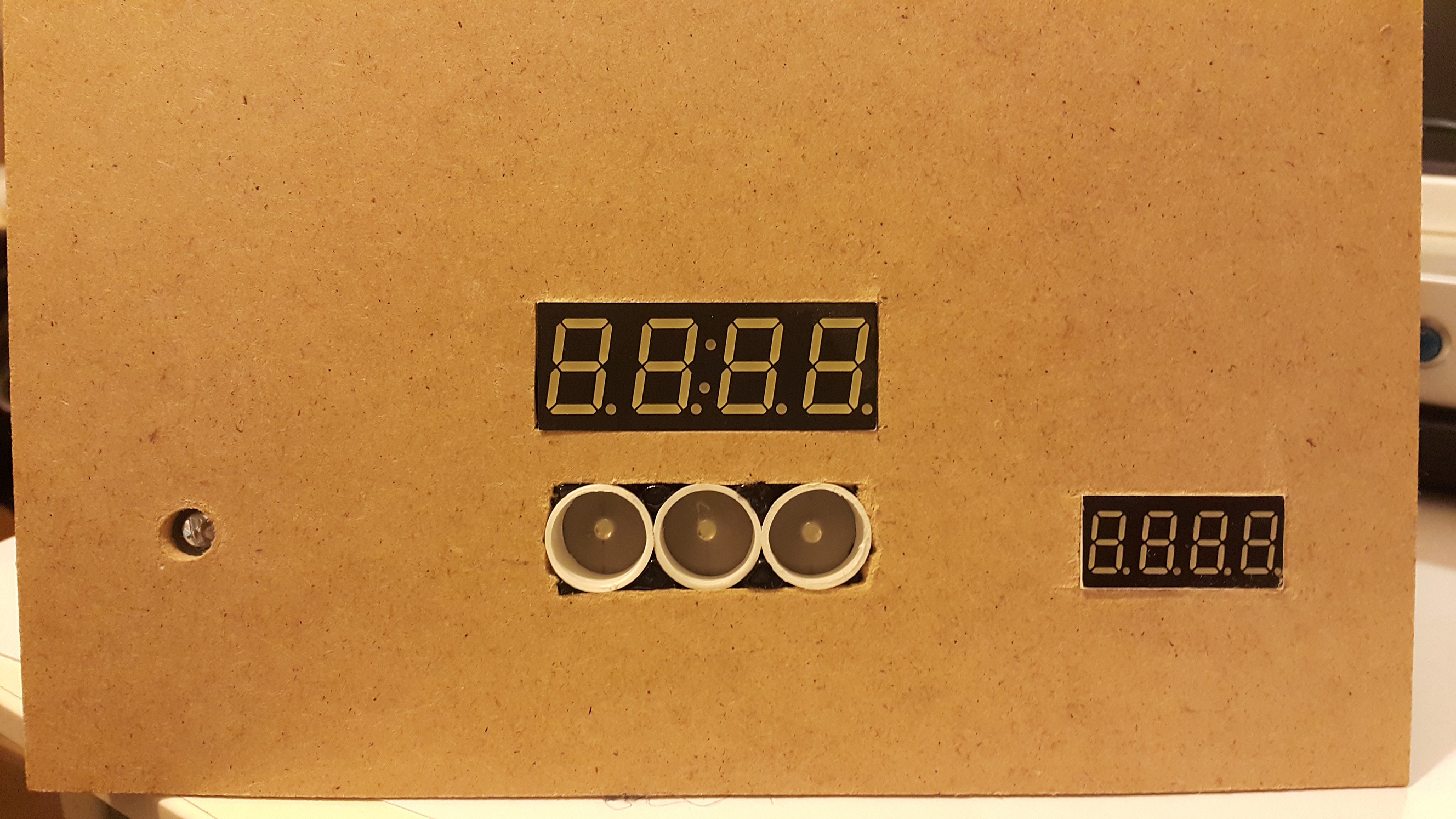
Thank you. At the beginning I used plain paper. But I got a better effect by covering the display with photo paper.

  Are you sure? yes | no

Richard Hogben wrote 03/28/2019 at 15:42 point

This is really cool, I like the combination of printed paper template with the LEDs.

  Are you sure? yes | no

Similar Projects

Does this project spark your interest?

Become a member to follow this project and never miss any updates