0%
0%
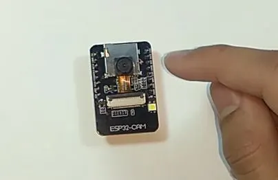
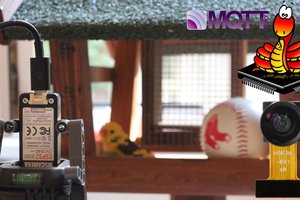
Wireless Security Camera in a Matchbox
An internet-connected camera which has wifi on board and is so small that it fits in a matchbox, for securing your valuables.
Become a Hackaday.io member
Already have an account? Log in.
Just one more thing
To make the experience fit your profile, pick a username and tell us what interests you.
Pick an awesome username
hackaday.io/
Your profile's URL: hackaday.io/username. Max 25 alphanumeric characters.
Pick a few interests
Projects that share your interests
People that share your interests


 Mauro Riva
 Pure Engineering
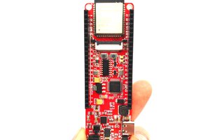
 allexoK