 ptrav
ptrav
I have completed the keyboard design. The current version has 60 buttons (one is hardwired to the controller Reset).
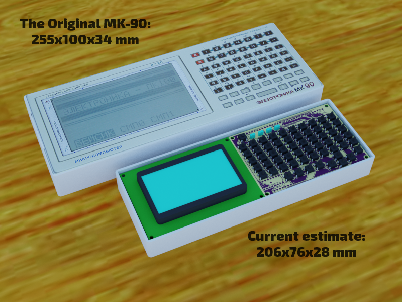
The display so far is a Black-and-White 128x64 low-power Black-on-Blue LCD (Note that the original MK-90 has exactly that resolution, but the screen is much larger). This is a quick rendering for comparison:
An alternative version would be with something like <A href="https://ru.aliexpress.com/item/32900230382.html?spm=a2g0o.productlist.0.0.74332b554sPNai&algo_pvid=9cab2e0a-fd50-41b0-bcb1-1507db69df45&algo_expid=9cab2e0a-fd50-41b0-bcb1-1507db69df45-16&btsid=be79cb74-3b32-40fb-b934-aadc62349cf5&ws_ab_test=searchweb0_0,searchweb201602_9,searchweb201603_55">LG320240</A>, but they are very costly.
The keyboard is assembled on a 140x95 mm mock-up board (the actual PCB size will be 100x70). The electronics and the Arduino Mega driver are working, Now need to decide how to assign the letters...

The schematics is attached in the PDF file.
The keyboard will have 6 rows and 10 columns, 59 buttons in total (#60 is used for reset). It is operated via a 3-line interface not very dissimilar to SPI: setting RESET high brings the counters to the initial state, then CLOCK is cycled 59 times and SIGNAL reads the status of 59 buttons (HIGH means "pressed"). The CMOS 4017 decade counter addresses 10 rows and a combination of a 4520 binary counter and a 4051 analogue mux connects the rows. The clock signal is sent to the 4017. Upon reaching back to zero after 10 pulses, the ripple signal from the decimal counter advances the 4520 to the next row. Because only one button is connected between the mux and the decimal output at any given time, diodes at the buttons are not required. Any number of buttons can be pressed simultaneously (the number of your fingers - and toes - is the technical limit) - they will all register .
The second half of the 4520 octal counter drives 4 LEDs to show the keyboard status (or could be used from the Basic to do some creative blinking). One button is hardwired to ESP32 reset.
In the stand-by mode the keyboard consumes less than 10 uA (micro-amp). Each LED consumes about 1200 uA if lit.
Upon the PCB completion and testing I will put the KiCAD files on Github.
The next big design question: "To brick or not to brick?"
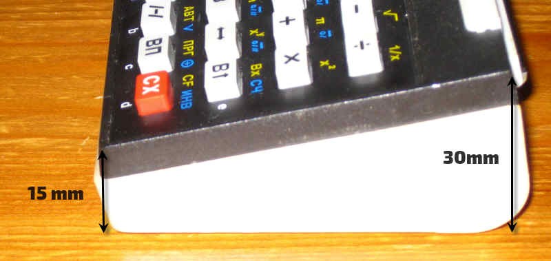
MK-90 is, well, a "brick". Another status symbol, MK-52, is a "wedge" (an so are B3-34!):
Discussions
Become a Hackaday.io Member
Create an account to leave a comment. Already have an account? Log In.
Very promising!
As for "Brick" and "Wedge" alternative: both are cool. I think that it should not be a replica of something particular, but a cool little machine with keyboard, screen and BASIC inside :)
Are you sure? yes | no