 Maksim Surguy
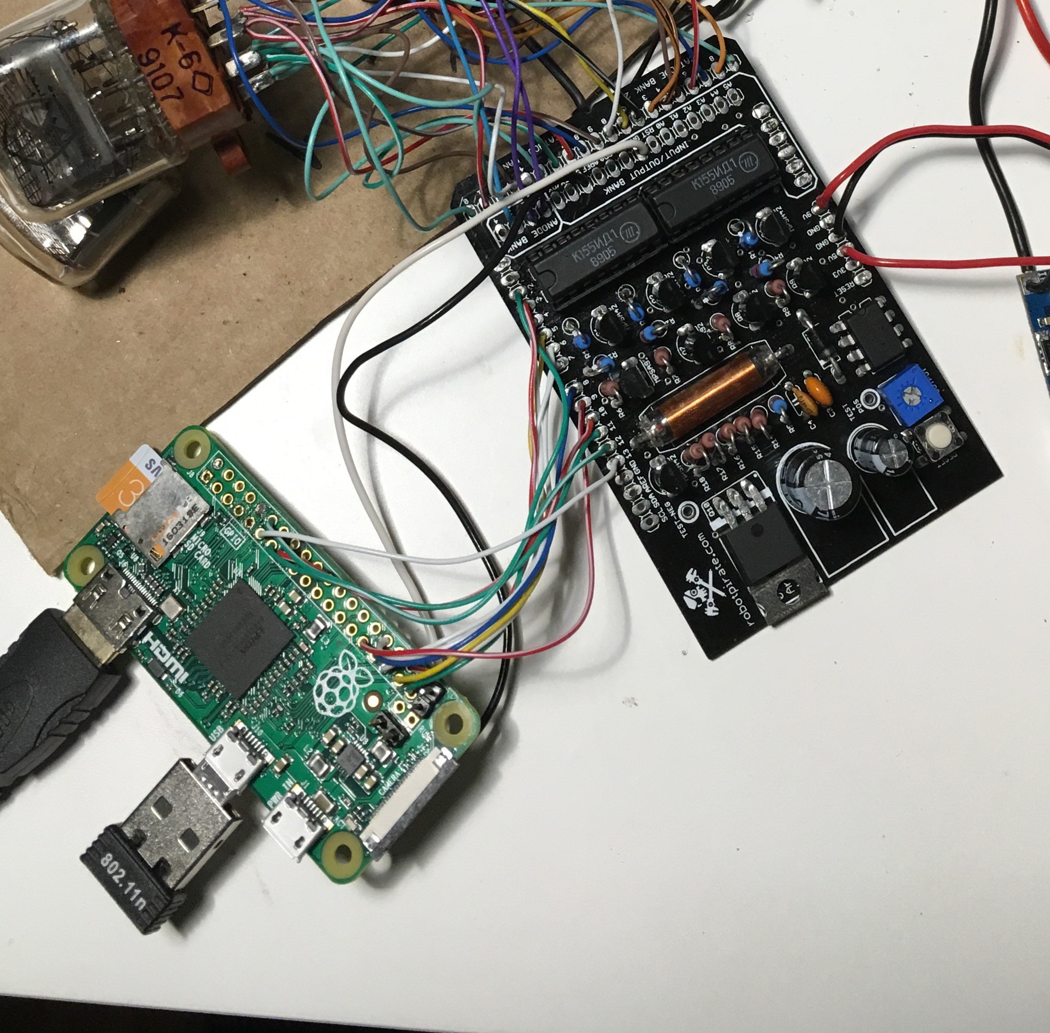
I am going to try to use Arduinix as the driver for the 4 IN-12 nixie tubes I got from EBay. Arduinix is an board that was originally designed to drive Nixie Tubes via Arduino Uno or alike.
Since Arduinix requires 12 inputs in total and Pi Zero has many more outputs than that, It should be very easy to connect Pi Zero GPIO to Arduinix input pins.
I first explored using ESP8266-based solution as a controller but there were not enough pins on ESP chip to drive the 12 necessary pins on Arduinix.
Arduinix uses 2x SN74141 or Soviet equivalent Nixie Driver ICs to route power to appropriate cathodes of the nixie tubes. These ICs take in binary 5V input on 4 pins and turn on up to 10 cathodes on the output.
Nixies' anode pins connect to high power transistors on the Arduinix and those transistors are turned on via yet other transistors.
By using only 12 pins (2 banks of 4 pins and 4 pins for anodes) you can control 8 nixie tubes in total by means of multiplexing. Since I am using only 4 tubes I should be able to turn on 2 tubes at a time for a brief period of time, then switch to another 2 tubes. When this is done very quickly, it will appear that the digits are always lit.
Without further ado, I connected pins 2-13 on Arduinix to the following pins on Pi Zero:
| Pin on Arduinix | Pin on Pi Zero |
| 2 | 26 |
| 3 | 16 |
| 4 | 20 |
| 5 | 19 |
| 6 | 13 |
| 7 | 12 |
| 8 | 6 |
| 9 | 5 |
| 10 | 22 |
| 11 | 27 |
| 12 | 18 |
| 13 | 17 |
I also connected Pi Zero's +5V and ground to Arduinix's 5V and ground pins necessary for the ICs.
Arduinix requires separate 9-12V input that gets converted to high voltage necessary for the Nixie tubes. I used an adjustable DC converter (link in the part list) that takes in 12V and converts it to 5V that is then distributed to the Pi and Arduinix's 5V input.
I followed schematics below to connect a single Nixie tube to the Arduinix:
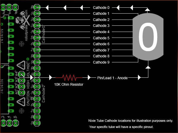
I then created the following Python program to display a number zero on a single nixie tube:
from gpiozero import LED
from time import sleep

# Assign anode and cathode pins
anode1 = LED(22)
anode2 = LED(27)
anode3 = LED(18)
anode4 = LED(17)

cathode1_a = LED(26)
cathode1_b = LED(16)
cathode1_c = LED(20)
cathode1_d = LED(19)

cathode2_a = LED(13)
cathode2_b = LED(12)
cathode2_c = LED(6)
cathode2_d = LED(5)

# Reset all anodes to 0
anode1.off()
anode2.off()
anode3.off()
anode4.off()

try:
    while True:
        # Displays a "0"
        anode4.on()

        cathode1_a.off()
        cathode1_b.off()
        cathode1_c.off()
        cathode1_d.off()

        sleep(1)

        #Turn off the nixie
        anode4.off()

        cathode1_a.on()
        cathode1_b.on()
        cathode1_c.on()
        cathode1_d.on()

        sleep(1)

except KeyboardInterrupt:
    # here you put any code you want to run before the program
    # exits when you press CTRL+C
    #anode1.off()
    print "\nExiting" # print value of counter

except:
    # this catches ALL other exceptions including errors.
    # You won't get any error messages for debugging
    # so only use it once your code is working
    print "Other error or exception occurred!"

finally:
    print "\nExited"
And here's the first test of the Arduinix and Raspberry Pi Zero!
Discussions
Become a Hackaday.io Member
Create an account to leave a comment. Already have an account? Log In.