 Simon Merrett
Ok, sorry about the clickbait title; who can resist the promise of LEDs? I promise a photo of a lit LED in this log, so you don't go home empty handed.
This log is a quick one to introduce an intriguing potential alternative to coin cells. I have been waiting for weeks for the module to arrive and then another week to make time to poke around with it. Inthe log where I shortlisted potential alternatives to coin cells for small projects such as "learn to solder" badges that would be suitable for children, I mentioned voltage-boosted AAA cells. The ME2108 series of boost converters nicely matches the brief on paper. Don't go looking at your usual distributors for ME2108 - you will find some very pricey Analog Devices and Vishay buck converters. Those are not the PMICs you're looking for....
Instead, turn your browser towards the exciting land of lcsc.com, where Nanjing Micro One Elec (and doubtless others too) have a range of DC-DC converter offerings. The ME2108A (you can go up to F with a variety of external transistor and chip-enable permutations) is what has appeared on many of these little 0.8-3.3V boost modules from eBay, Aliexpress etc. Here's the datasheet. Two key features make them attractive to me, in the context of Coin Cell Challenge:
- Compact packages. SOT-89 is the standard one available on the modules but SOT-23 is listed too. There is an argument that if you want all the "learn to solder" components to be soldered by the student that this is a downside. It's not a show-stopper for me but do hold that thought.
- Price. $0.07 in qty 5 and dropping from there isn't going to break anyone's kit BoM budget.
- Minimal additional components. Two caps, one schottky diode and one inductor (if you use a version with internal switching). Headline IC price is never the full story and the additional passives are no deal breaker here. Equally, if you wanted to, you could use these components as part of the learn to solder experience, as they're all available in through hole form.
- 3.3V and 5V regulated with many 10s of mA available (claimed - not completely tested). This gives a significant advantage over coin cells if a higher voltage is required or you want a reasonably stable voltage across the range of cell discharge voltage.
However, I can already sense there are disadvantages with this approach. The key one, other than the additional minor complexity and expense (depending on your comparison) to your BoM, is that these aren't going to be the easiest to switch off to a very low quiescent current in the existing module format more on that later. Also, the form factor of the AAA battery - it's OK, not as slim as a a coin cell (10.5mm plus your holder/clip for AAA vs 4.5mm for a CR2032 SMD holder) but we also need some PCB space for those supporting components.
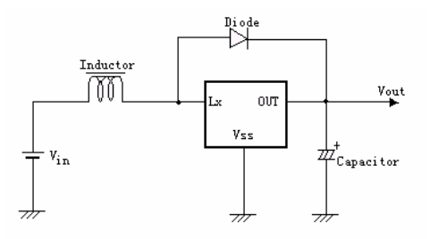
Here's how these eBay modules come wired up (from the datasheet diagrams):
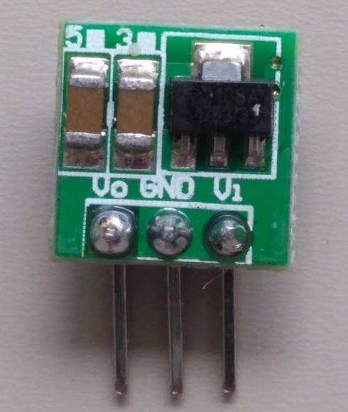
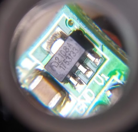
And here's the main IC with the caps on the front:
And here are the the diode and inductor:
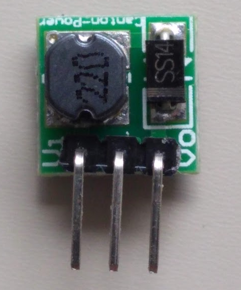
I haven't checked the values of the onboard components but it looks like a 22uH inductor. The pricing for these is $2-3 in single quantity with reasonable delivery time or less than $0.5 in qty 8 from e.g. Aliexpress.
The initial test was for a DC load through an LED with a potentiometer to adjust the current:
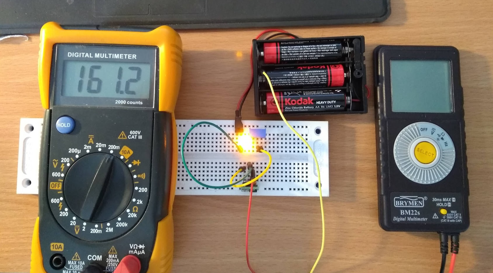
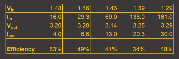
I measured the voltage across the battery terminals and the voltage across the converter output under load. I also measured both the current flowing in the battery-converter circuit and the converter-LED circuit. I varied the LED current from 4mA to 30mA (sorry, LED) and the results are below:
This is the rather messy graph of that table (log scale on the left, liniear on the right :-) :
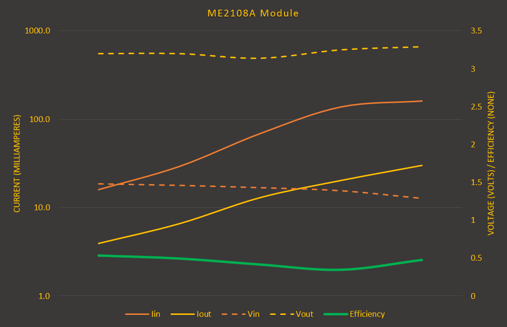
My main takeaway is that it works! But not the best. Maybe that's the implementation of the module components. Maybe the ICs on the module aren't the Nanjing Micro One Elec version (highly likely). But it works. The battery in my test was AA, rather than AAA, so there may be a greater voltage drop due to internal resistance with an AAA. But interestingly the efficiency dipped and then improved with lower battery voltage and higher current draw towards the end. This is what the datasheet says to expect for efficiency:
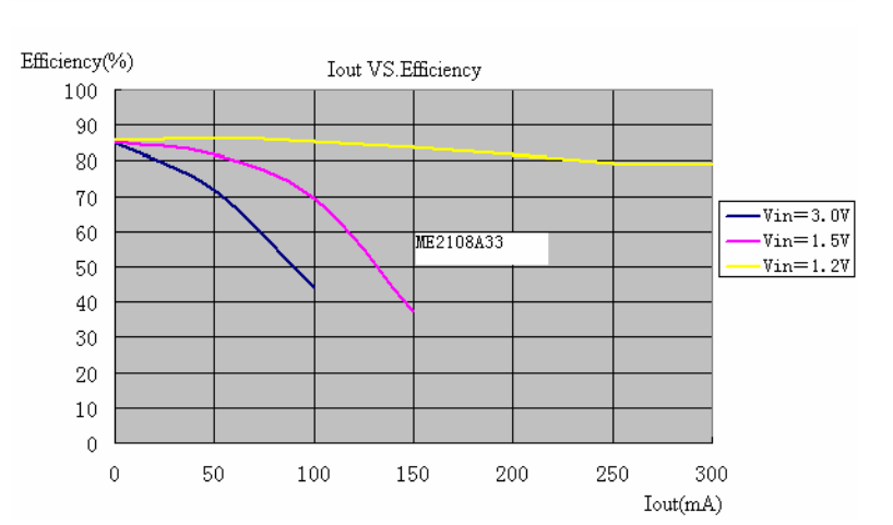
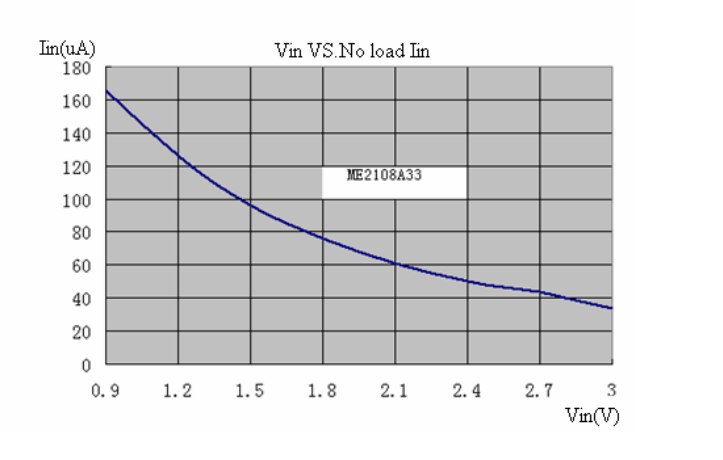
But they also say to use a 47uH inductor and a low Vf Schottky, neither of which our modules seem to do! I also measured battery current when no load was attached - 0.1mA, which is in line with the Nanjing Micro datasheet:
Acceptable for some but we ought to remember that the likely choice of battery to go in a "learn to solder" badge is a ($/£insert currency) shop job. These little blighters are usually zinc and once discharged will leak themselves everywhere. This is no good for our #Coin Cell Challenge... so we need to look at getting the ME2108 version with the logic shutdown. Or, even better, a switch that can take our full battery current and switch the circuit at the battery. But that's not good for the BoM as we expect some fairly high battery currents for moderate load circuit currents. So, we want the ME2108C with its Chipe Enable pin and promise of 500nA shutdown current.
I'm intrigued enough to go further with these devices. But just as I was searching for the datasheet link for the ME2108, my eye was caught by the ME2188 and this seems to be able to drop the schottky diode and switch at a higher frequency (smaller inductor), for a small tradeoff in max current. I now want to try this! Here's the mainly chinese datasheet for those playing along at home!
Discussions
Become a Hackaday.io Member
Create an account to leave a comment. Already have an account? Log In.