Mark Omo
The goal of the Open Modular Electronics Bench is to provide a modular and easily extensible benchtop instrumentation system, in order to facilitate a community-driven ecosystem of instrument modules. Haphazard design choices will kill adoption of any framework before it begins, so a solid foundation is required to achieve this goal: the system architecture.
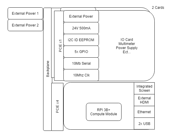
The system is designed around modules that can be swapped and provide the functionality of various instruments (such as a multimeter, oscilloscope, or even a power supply), and a controller which is the brains of the operation, collecting, coordinating and displaying data from all of the instrument modules. The modules connect to a single backplane board, which can accommodate scaling from one to four modules with a single controller. The module interface is a PCIe x1 slot, and the controller interface is a PCIe x4 slot, both chosen for their high pin count and common availability.
The controller will be designed around a Raspberry Pi compute module, because it is easy to use and program, avoids the unnecessary complexity of a from-scratch single-board computer, and has guaranteed availability until January 2026. It connects to a 5-inch touchscreen on the front panel as the primary means of interacting with the system, but also supports an external HDMI display, or remote access over a network. The controller also integrates an AC-DC converter, providing the 24V power used by the instrument modules.
The system provides a wide array of I/O to the modules, including five 3.3V GPIOs, a serial port capable of up to 12Mbaud, a 10MHz reference clock, and an inter-module sync line. This array of control options allows modules to be as simple or complex as they need to be. For example, an oscilloscope module might have a powerful processor onboard, streaming pre-processed back data to the host. On the other hand, a scanner card could be designed which is nothing but a bunch of relays just connected to the card’s GPIO. Instrument modules by default have 24V 500mA power available for use, which is plenty for most applications. Modules that require higher power can utilize a set of pins on the card connector which are directly passed through to external power inputs on the back of the system. These pins allow for up to 100V at 8.8A: 880W! With this much power even a beefy power supply is possible. We shamelessly stole took inspiration from the Raspberry Pi Hat ID EEPROM format, so the system can identify and automatically load the software for the card inserted, presenting a seamless experience to the user.

 matthewreed
 Denis
Denis
 William