 agp.cooper
Properly Meshed Planetary Design
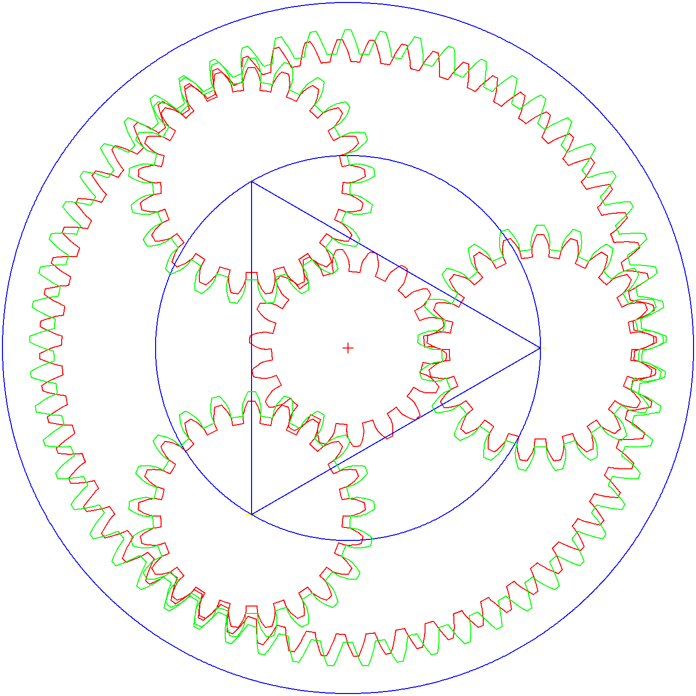
For this log I present a properly meshed planetary drive:
Notes:
- The red gears are the first layer and the green gears are the second layer.
- Only the first layer has a Sun (pinion) gear.
- The planetary gears (red and green) are locked to each other (they do not rotate independently of each other, i.e the layers are fixed to each other).
- The outer layers rotate freely of each other.
Generating the gears
Initially I used Gearotic (as I have a licence) but Gearotic is tricky to use if you have not used it for a while and the exported DXFs are not great. And the gears are not one shape (each). The are short "polylines".
While this was not a problem in the past when I was using Windows because I had a macro for my CAD package that could join the polyline segments. Unfortunately the macro feature does not work under Wine (as I have migrated to Linux).
In the end I decided to write my own gear code in C and export my own DXF gears.
DXF File Format
The DXF file format is an absolute nightmare. While exporting points and segments are easy, exporting polylines (i.e. shapes) that CAD packages can read in is not.
I found some old code that I have written for polylines and thought great, lets try this.
Well yes, it imports into my CAD package but my CAD package converts the polylines to segments. Not good.
I found some more old code that I have written for lwpolylines and thought great, lets try this. Well it was unfinished, I was having problems with the "handles" and never solved it.
Then I though, perhaps the problem with polylines is my CAD package. So I installed LibreCAD and yes it imports the polylines properly. LibreCAD does not have a macro language but as it can import polylines, segments and points it does not matter if I can created simple DXF files in C. Move over DeltaCAD, LibreCAD coming through.
Gear Code
I will upload the gear code later, it still needs a user interface. But I have uploaded the DXF file. If the gears are the wrong size you can just re-scale them.
Top Level Code for the MPRT Concept
This is for reference:
{ // Top level Gear Code
  double PA=20.0;                               // Pressure angle
  double P=0.10;                                // Diametral Pitch
  double TX=0.0;
  double CX=0.0;
  double CY=0.0;

  // First Gear Set
  makeGear(2, 18,PA,P,CX,CY,0.5);              // Sun, rotate 1/2 tooth for mesh
  CX=(60-21)/P/2;
  CY=0.0;
  makeGear(2, 21,PA,P,CX,CY,0.0);              // Planet 1
  TX=CX*cos(120*M_PI/180)-CY*sin(120*M_PI/180);
  CY=CY*cos(120*M_PI/180)+CX*sin(120*M_PI/180);
  CX=TX;
  makeGear(2, 21,PA,P,CX,CY,0.0);               // Planet 2
  TX=CX*cos(120*M_PI/180)-CY*sin(120*M_PI/180);
  CY=CY*cos(120*M_PI/180)+CX*sin(120*M_PI/180);
  CX=TX;
  makeGear(2, 21,PA,P,CX,CY,0.0);               // Planet 2
  makeGear(2,-60,PA,P,0.0,0.0,0.0);             // Outer ring

  // Second Gear Set
  P=P*(57-21)/(60-21);                          // Change Diametral Pitch
  CX=(57-21)/P/2;
  CY=0.0;
  makeGear(3, 21,PA,P,CX,CY,0.0);               // Planet 1
  TX=CX*cos(120*M_PI/180)-CY*sin(120*M_PI/180);
  CY=CY*cos(120*M_PI/180)+CX*sin(120*M_PI/180);
  CX=TX;
  makeGear(3, 21,PA,P,CX,CY,0.0);               // Planet 2
  TX=CX*cos(120*M_PI/180)-CY*sin(120*M_PI/180);
  CY=CY*cos(120*M_PI/180)+CX*sin(120*M_PI/180);
  CX=TX;
  makeGear(3, 21,PA,P,CX,CY,0.0);               // Planet 3
  makeGear(3,-57,PA,P,0.0,0.0,0.0);             // Outer ring
}
"makeGear" parameters are:
- Colour
- Number of teeth
- Presure angle (degrees)
- Diametral pitch
- Gear X centre
- Gear Y Centre
- Gear rotation as a fraction of a tooth
Next
Now that I can design the gears for the MPRT, I can now look at the SCARA elbow design.
AlanX
Discussions
Become a Hackaday.io Member
Create an account to leave a comment. Already have an account? Log In.
Post the numbers you used, and I will port it.
Are you sure? yes | no