 Jan
JanUpdate – 2019-07-15
The ripple-measurement screenshots I originally posted below were done with the ground-wire-alligator-clip-method and not the correct direct-connection method. See this Application note by Analog [p.5] for more details how to do it correctly. Analog doesn't call it "Incorrect Ground Loop Method" for no reason...
Measuring this way (and setting the probe to 1x = no amplification) the ripple reduces to the more reasonable 30mVpp I mentioned in my updated log below.
Update – 2019-07-10
Using the DC/DC buck converter with nearly 30mVpp ripple the ADC readings by my Attiny861A test board are always within 0.05V of "jitter" between readings (each reading is an average of 10 single readings).
So, the circuit seems to work just fine. Problematic thing is the "no load"-current of nearly 0.55mA which is too much drain on my projects batteries for my taste.
We'll see where it goes from here...
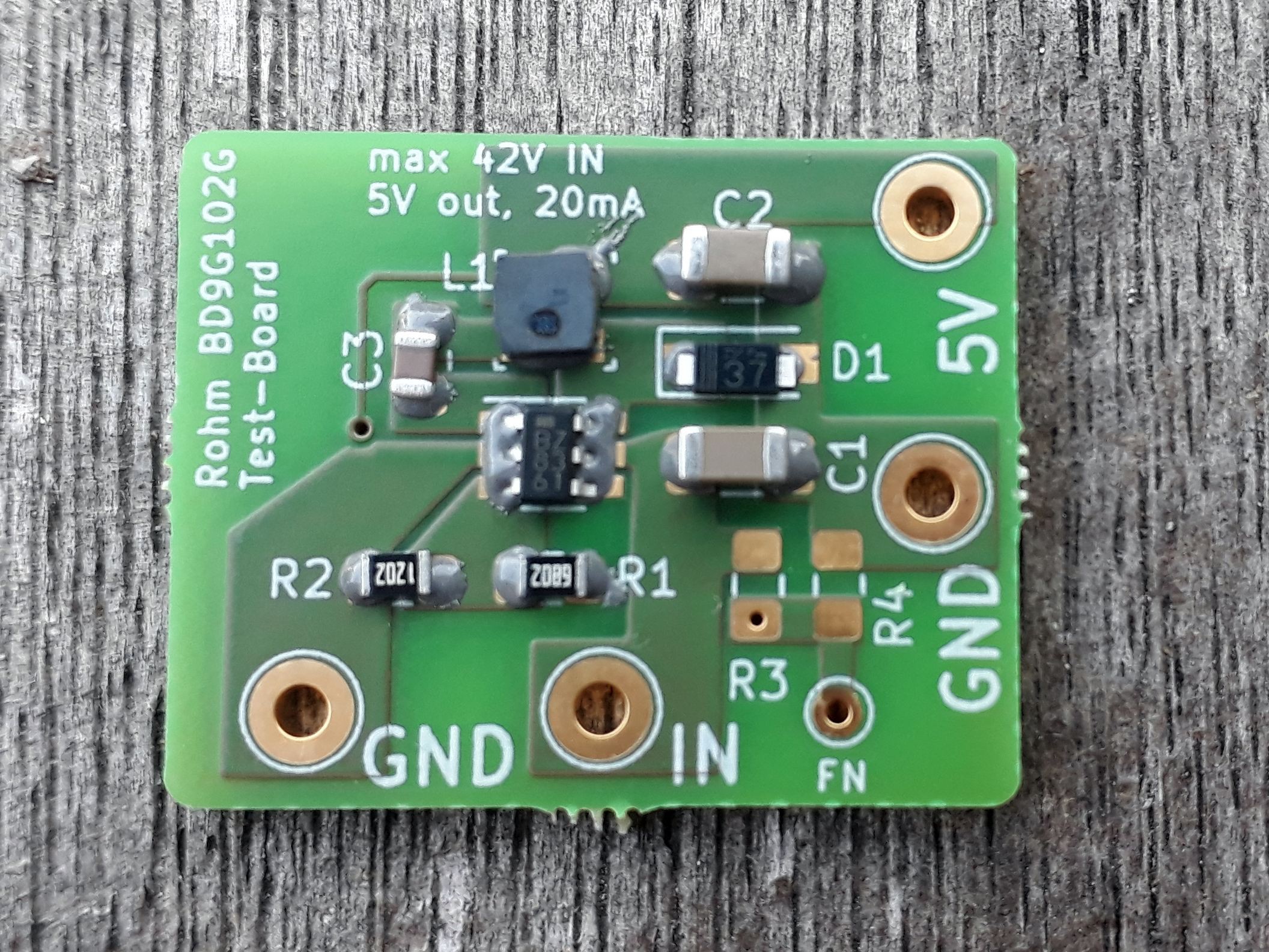
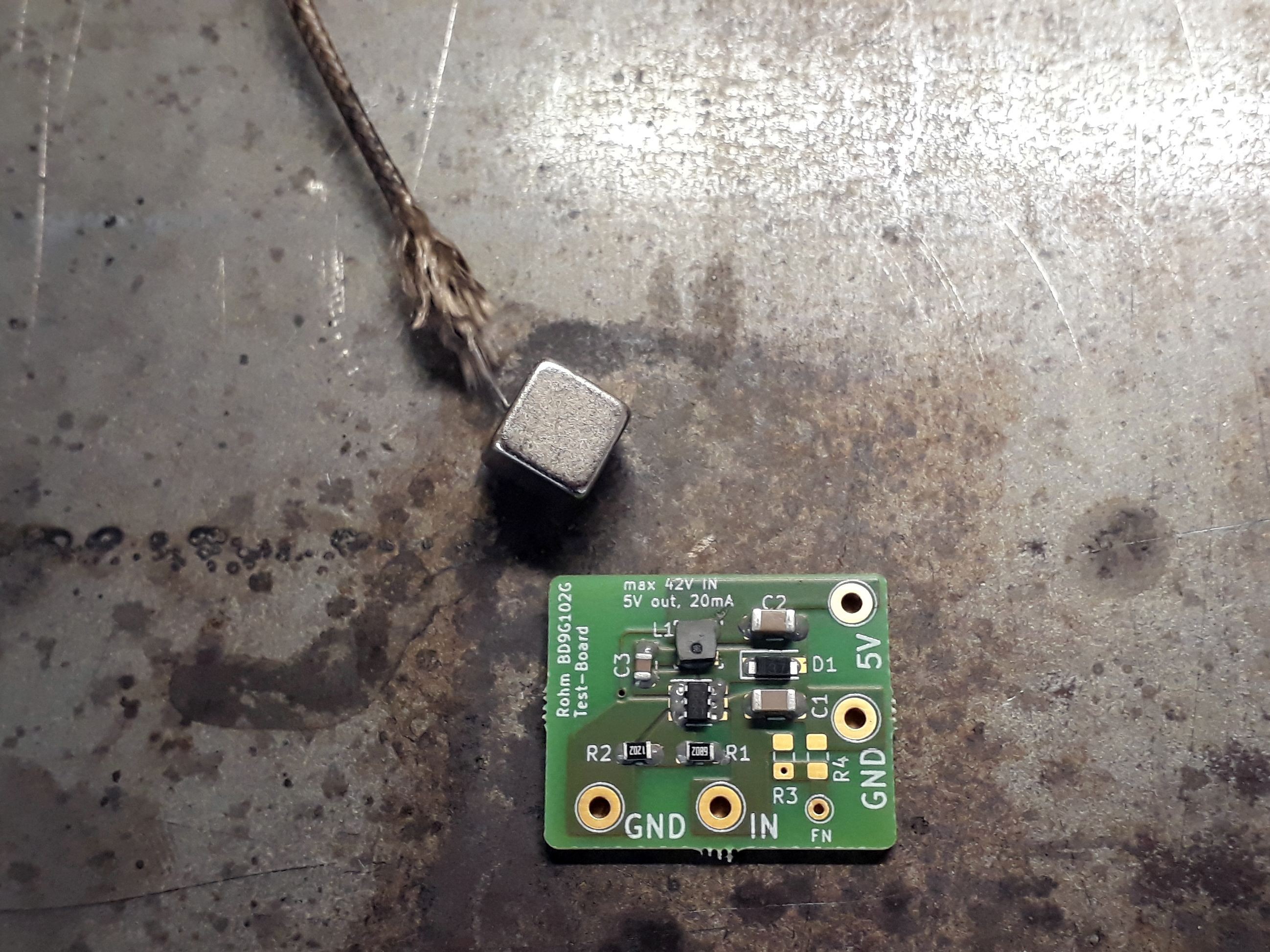
Today, 7 days after ordering, PCBs and parts arrived in my mailbox.
Build process
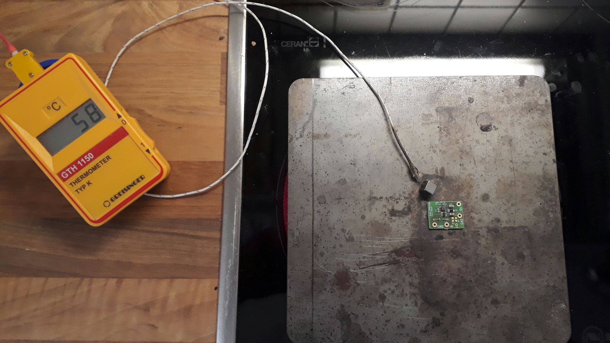

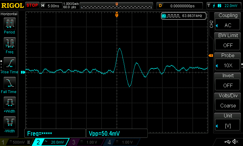
Measurements
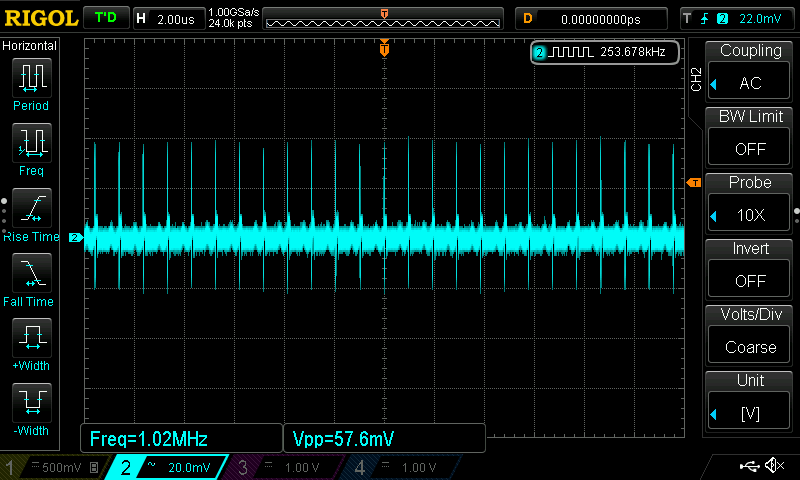
If I remember correctly the peaks are the switching noise from the regulator/coil. This makes sense as it it exactly the 1Mhz switching frequency of the regulator.
Discussions
Become a Hackaday.io Member
Create an account to leave a comment. Already have an account? Log In.