 Jan
JanUpdate:
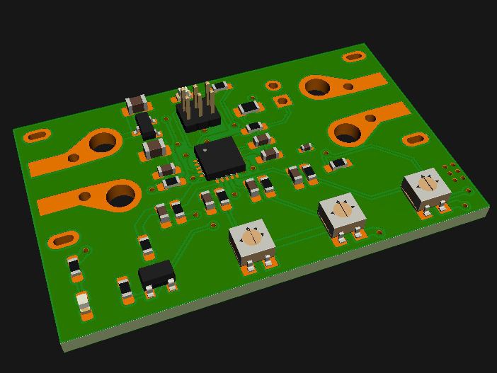
New board will look something like this. The above screenshot is fully routed and DRC'd. Should work :) Size is 25 x 40mm (1" x 1.6"). MOSFET and two diodes are on the bottom copper side. I'd love to get rid of the trimmer pots but then I'd loose all comfort which was a main goal of this project: using one board for all project-needs without the need for an PC to change settings...
Where to go from here
So, I did a few tests with DC/DC buck regulators and "standard" LDO linear regulators. DC/DC has been very easy with the right board layout, ripple is not too much of a problem...
But there's two drawbacks which pushed me in the linear regulator direction again:
- higher current consumption in low current draw scenarios (major drawback)
- more expensive, more parts (minor drawback)
What is my solution?
I will use the cheap and durable (in my limited test samples at least) Nanjing Micro One Elec ME6203 regulator. It is a china brand, which means there's no chance getting it from Digikey or other major vendors, but this is a minor concern for me at this point. I just want my hand full of working boards :)
I will add an 5V6 zener diode at the output to clamp the 5V rail to a 6V maximum (which is including the zeners tolerances). The ME6203 shorts out at 20mA, heats up and survives this condition for hours.
My overall power requirement will be well under 5mA. The Attiny will be clocked at 1Mhz internal RC oscillator which is plenty for burst-reading 10 ADC values at 10Hz. Conversion time for the first reading is around 25µs and 13µs for the next reading.
A very interesting approach would be the Attiny1616: it has the internal capability to to burst-readings (up to 64) and give the average from that... See here for details!
When will the next set of boards be ready?
Soonish :)
Discussions
Become a Hackaday.io Member
Create an account to leave a comment. Already have an account? Log In.