 Jan
JanSo I would like to measure the current flowing in the next iteration of the board. There's many possible solutions to this. I do not need to measure over the full range of 0 to 10 or 15A in mA resolution. My aim is to cut the load off when a certain current is reached.
So let's assume this current I want to cut the load at is 10 ampere. I needed to select a shunt for that. To not waste too much energy (because it is directly in line with the load) it needs to be as low resistance as possible.
Selecting a shunt resistor
So I chose a 0.005Ohm shunt. At 10A there will be (U = R*I) 0.05 ohm * 10A = 0.05V across it, which is 50mV. It will turn (P = R*I²) 0.005 ohm * 10²A = 0.5W into heat. The shunt needs to cope with that, so I chose a 1%, 2W version which comes in a 2512 case.
But how the heck are we going to reliably measure 50mV and turn it into a value that allows the Attiny to work with?
Selecting a proper Analog to Digital converter
There are two ways I'll describe here.
1 – using a separate ADC chip
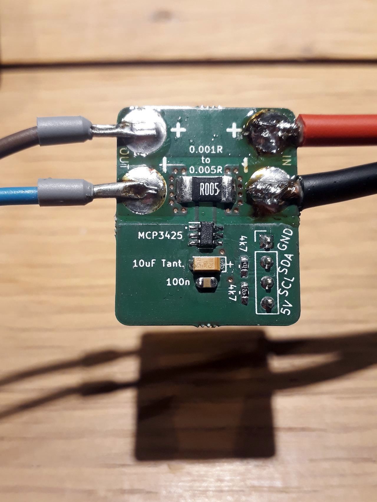
Here's a small break-out board for the Microchip MCP3425 16Bit ADC chip. Here's the schematic:
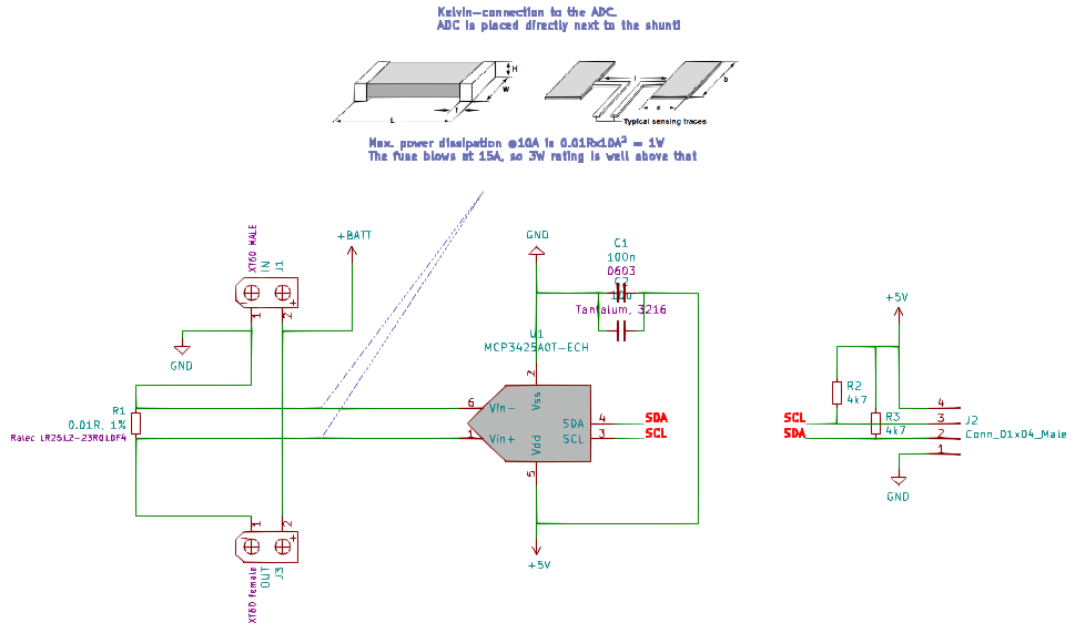
As the ADC doesn't accept a voltage >> than VCC we need to sense the resistor voltage drop connected to ground. Sensing is done with the widely adopted "Kelvin sense connection":
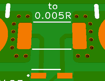
This eliminates a few problems regarding sensing directly from the main current path. Analog has evaluated an really special footprint design especially for this purpose here. Be sure to check that out as well!
The drop will be super low, so ground shift will be no problem here. These are the resolutions you can get from the ADC:
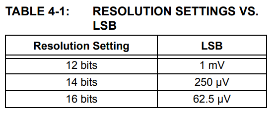
More bits = longer measuring time:
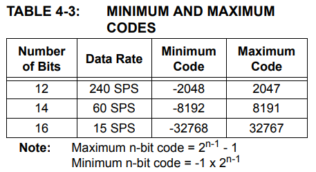
So, for a quick "just overcurrent protection" we can choose 12 bit resolution. This means a current of 10A gives us a code of 50, which is exactly 50mV in this case because of the 1mV resolution / LSB.
Overcurrent-shutdown will take at least 4.2ms (240Hz sample rate). This could be too long to protect the MOSFET from destruction, I'll have to look into that. A fuse for the absolute max current needs to be implemented anyway.
2 – using only the Attiny816
Stay tuned...
Discussions
Become a Hackaday.io Member
Create an account to leave a comment. Already have an account? Log In.
The LM5066 will operate up to 60 or 70V, but it has a higher minimum voltage (10V). One nice thing about these parts is that they have a charge pump for driving an NFET. They also handle the switch on into a capacitive load pretty well. They are also in an SSOP package which is a lot easier for manual assembly.
Are you sure? yes | no
You might look at the INA219. It reads current and voltage up to 25V or so using a high side resistor. Data is accessible over I2C.
One of my favorites is the LM25066 hot swap power controller. It has high and low voltage cutoff, over-current cutoff and reads voltage, current temperature and power over I2C. It can be set up to disconnect if any of the fault conditions occur. Contact me if you are looking at using the LM25066, I was involved in developing it.
Are you sure? yes | no
Hi @Bharbour yeah, this board is just one step in my learning curve. Looked at all the INA chips already, some of them work up to 40V and more, those are the ones I need.
The idea (in the long run) is to not use any external device at all.
Regarding the LM25066: unfortunately it doesn't work up to the 34V I want my board to handle. I sure will contact you anyway :)
Are you sure? yes | no