 Dan Maloney
The basic design for this dummy load comes from the RF Biscuit project by @georg ottinger. It's a simple PCB design that has pads for SMA edge connectors at each end, a ground plane around the whole board, and pads for placing SMT components in arbitrary combinations to build up filters, attenuators, and amps for RF use. I downloaded his design and had three boards printed up at OSH Park for a couple of bucks. I have a couple of things I want to try with these boards, and the first is a 50-ohm dummy load for my handy-talkie (HT).
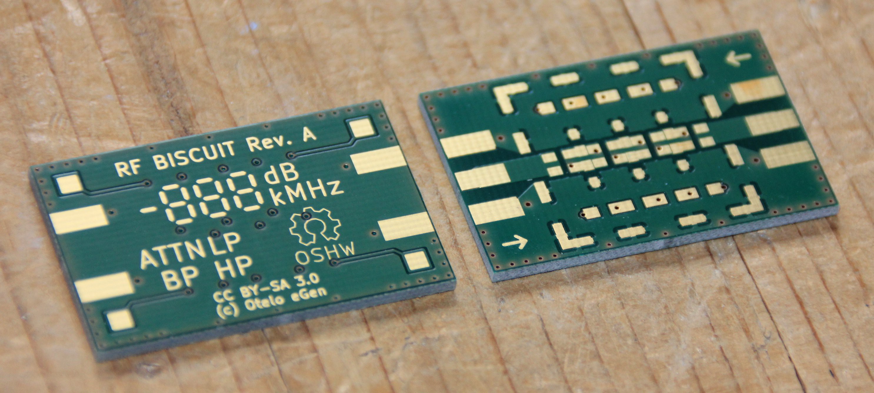
The circuit for a dummy load is stupid (heh) simple - it's literally just a 50-ohm resistor across the antenna connector's inner conductor and shield. But, as with all things RF, details matter. Not just any resistor will do. First, it has be able to dissipate the power that the radio will put through it - 5 watts in this case. That means you need to spec a power resistor, which more often than not are wirewound. No bueno - that looks more like an inductor than a resistor to an RF circuit, and things will start to get twitchy. What to do?
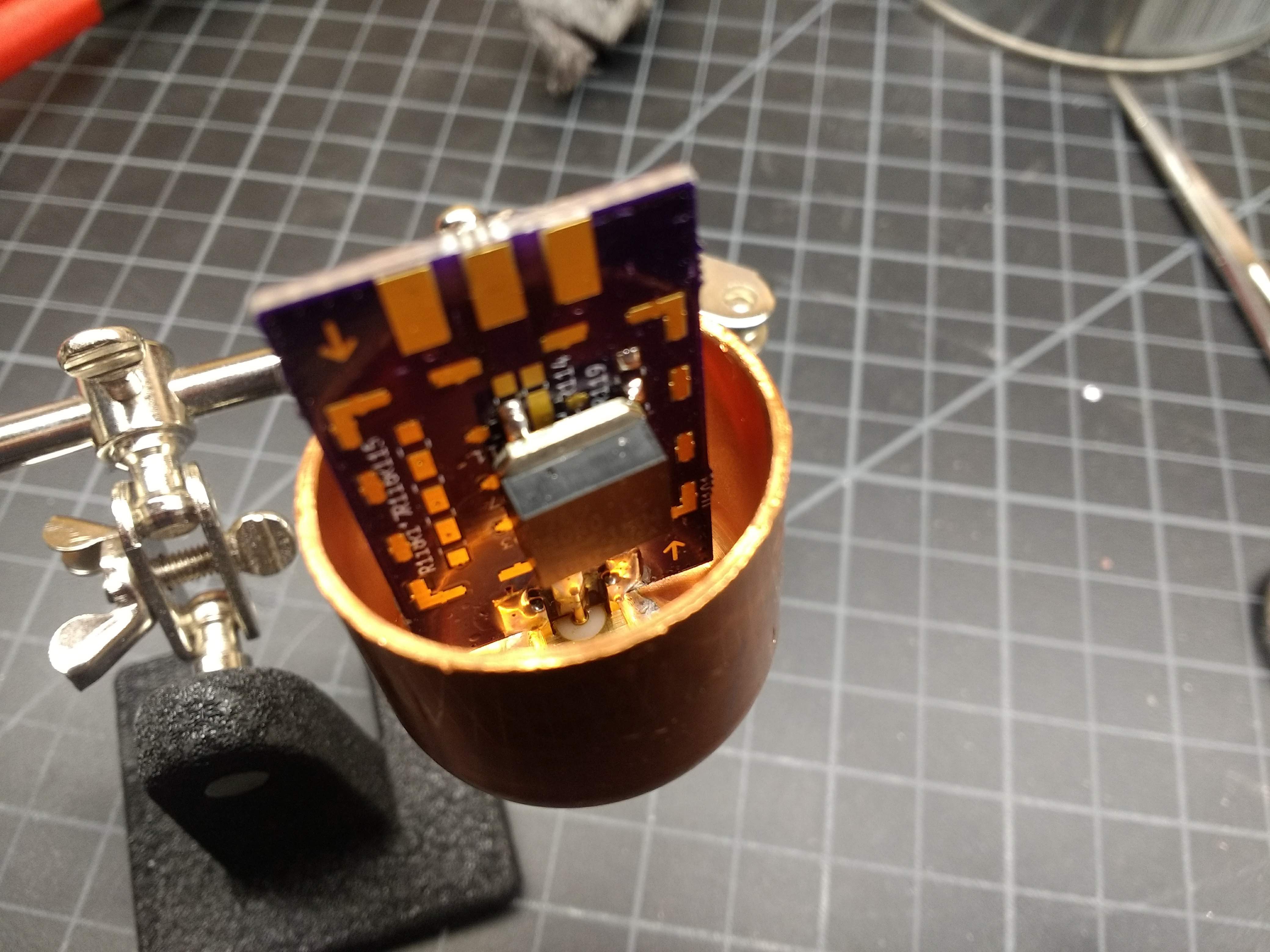
We need a non-wirewound, 50-ohm power resistor, preferably in an SMT package. Luckily, @georg ottinger lists a thick-film, SMT resistor that can dissipate a whopping 35 watts - a Bourns PWR263S-35-50R0F. I picked one up off of Mouser for less than $5, and sourced some card-edge SMA jacks from Amazon to complete the internals.
I soldered up the board and gave the dummy load a test on my Baofeng. To my surprise, the dummy was almost as effective an antenna as the stock rubber ducky - I was able to hit a repeater a couple of miles from my house! Clearly this is not how a dummy load is intended to act. I figured a decent enclosure would help, so off to Home Depot.
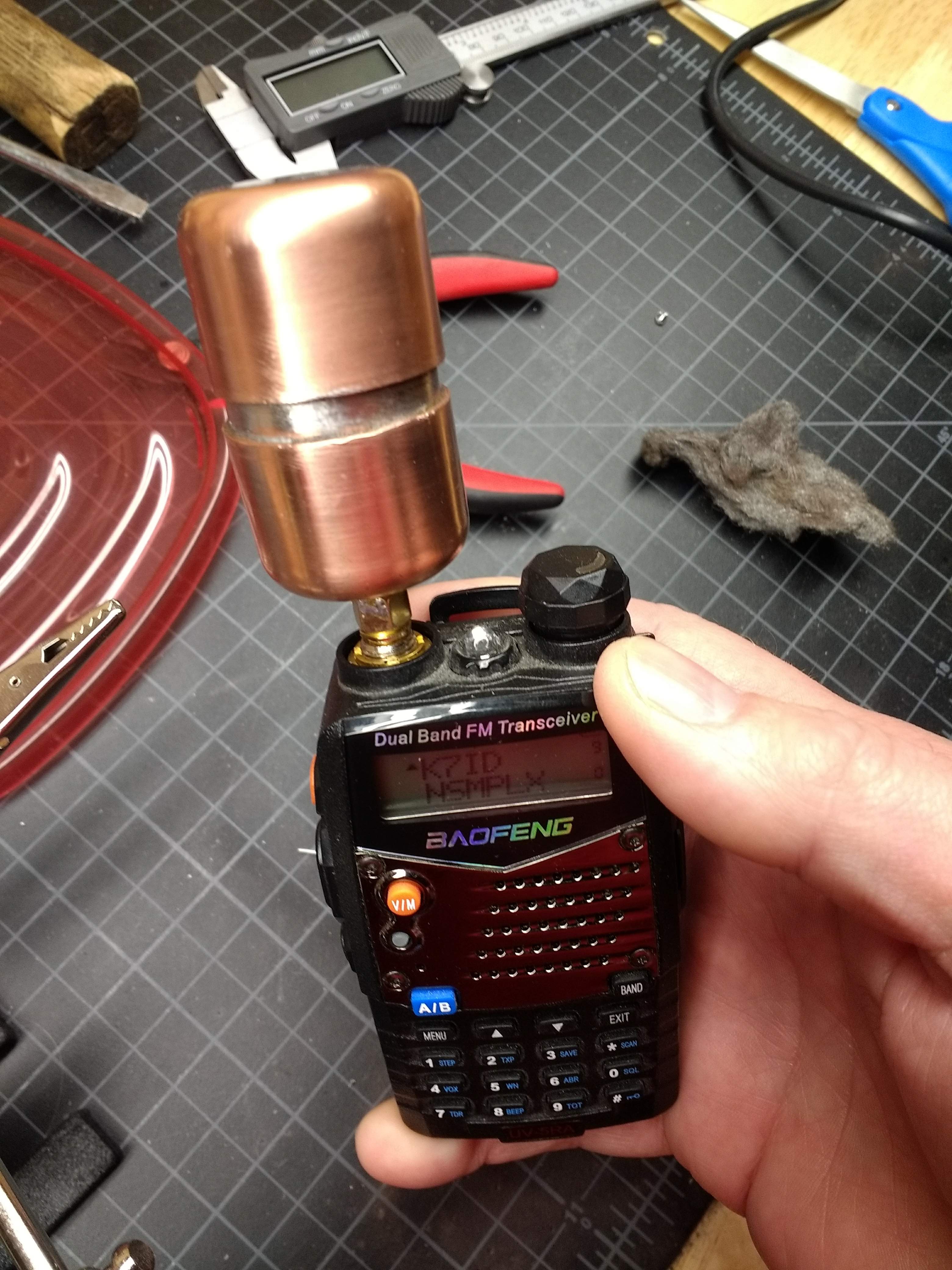
My idea was to case everything up inside a small length of copper pipe. The RD Biscuit board fit nicely inside a 1" diameter copper pipe, so I bought a short length of pipe and two 1" caps. Copper is crazy expensive, which sucked a little since I only need a piece of pipe like 3/4" long to couple the two caps together. I drilled a hole in one cap for the SMA jack, polished everything up nice and clean and fluxed the crap out of it, then tried to solder it in place. I had to move up from my Weller soldering gun to a propane torch, and there was a lot of juggling around hot copper and molten solder, but in the end I got it soldered together.
Doesn't look half bad cleaned up:
I had intended to fill the case with mineral oil before soldering it up, but I couldn't figure out how to do that. If I had somehow marked the position of the board inside the pipe I could drill a small hole in the top cap and fill it now, but why bother? The resistor is rated at like 7 times what this radio and any of the HTs I'm like to own can radiate, and even if the resistor gets a little warm in use - and it does - it's no big deal. I'm leaving well enough alone.
Double checked the dummy load and it now does exactly what it's supposed to do. I also checked it on an SWR meter and it's behaving just like it should. L'il Dummy seems like a success - my first ham radio-related build worked! W00t!
Discussions
Become a Hackaday.io Member
Create an account to leave a comment. Already have an account? Log In.