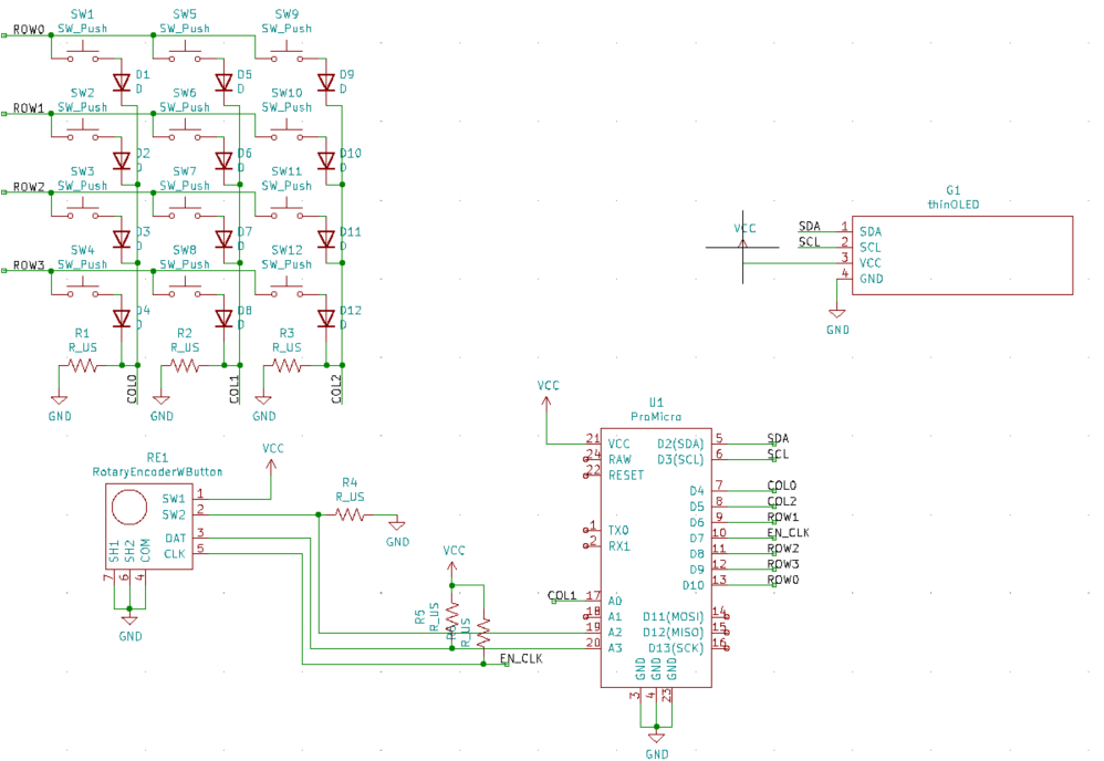
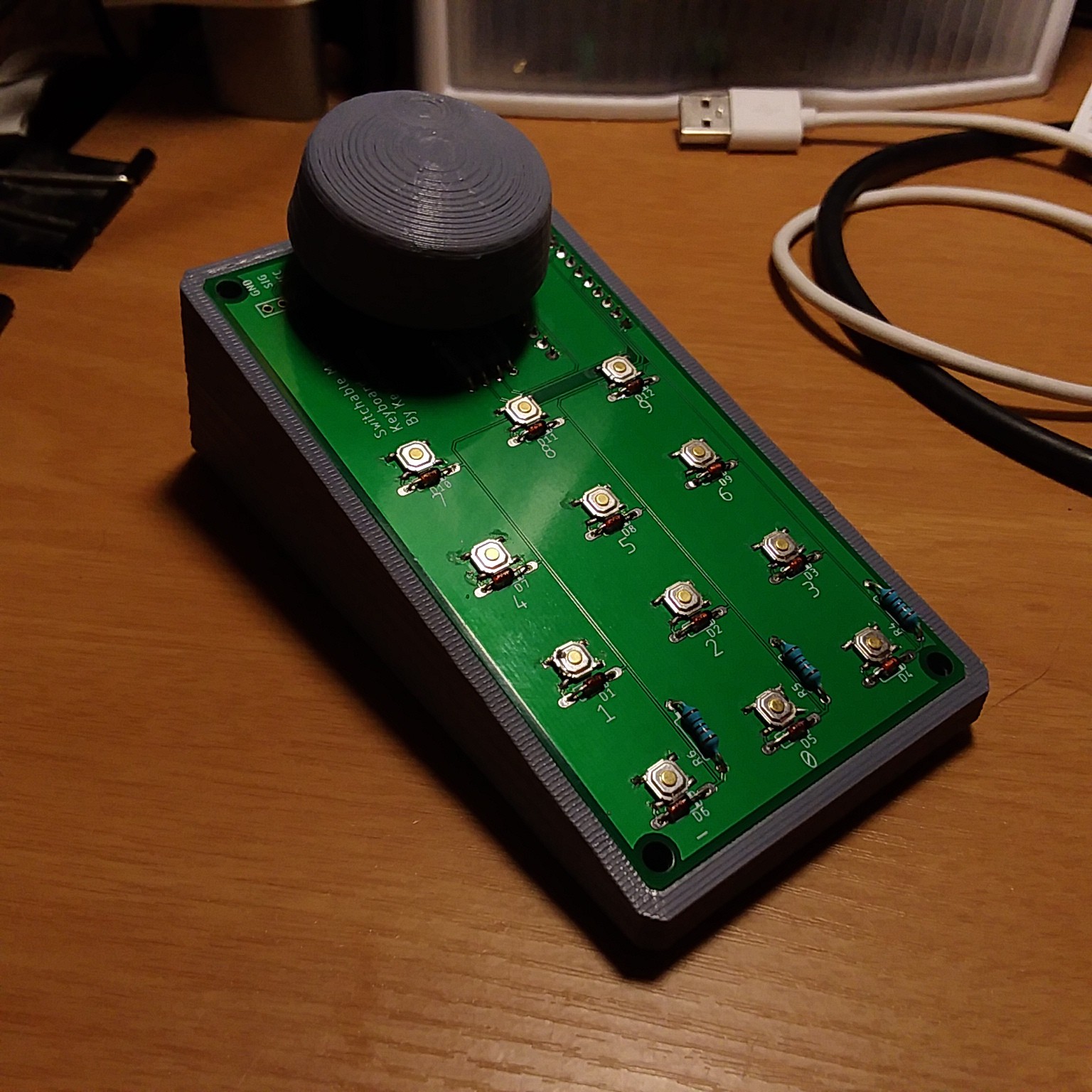
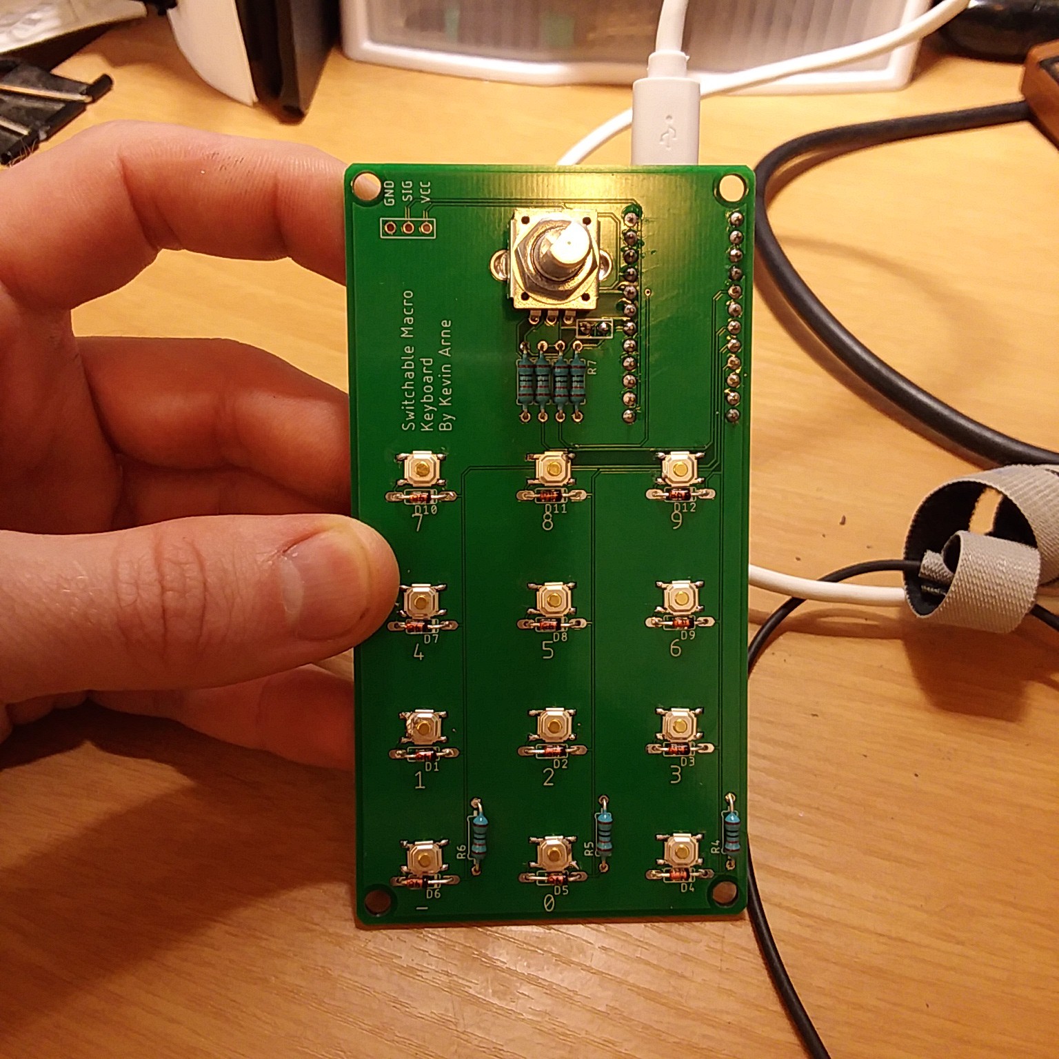
• I Switched to KiCad

    Kevin Arne03/30/2021 at 04:30 0 comments

    KiCad

    Since I hear Eagle is going to get consumed by Fusion 360, I decided I should give KiCad a try for PCB design. I love Fusion 360, but if I'm going to have to learn a new workflow, might as well use an open source one that's pretty widely praised.

    KiCad uses a different paradigm for how parts are defined. In Eagle, you design footprints and schematic symbols, then link them in a "device." The device is then what you use in your schematic and board layout. In KiCad, schematic symbols and footprints are much less connected. You can choose basically any symbol, then you tie a footprint of your choice to it when you go to make your board. The only way the two are connected is through the numbering of the pins. I think this has the potential for some frustrating errors, but it does feel like it made it much easier to simply design a footprint and associate it with a symbol you got from the generic libraries.

    I also prefer the way mouse clicks work in KiCad. It just feels much more intuitive.

    I did the port from Eagle to KiCad in a Twitch livestream if you're interested in seeing how I redesigned the board. Bear in mind that I'm still an amateur, so while the ways I do things might work, they aren't necessarily the best way (or even good for that matter).

    New Boards

    In this version of the board, I changed the placement of the rotary encoder to position it near my thumb (I'm using the keyboard with my left hand). I also switched from one of those big LCD panels to a smaller OLED panel.

    I got rid of the RC filter with the rotary encoder inputs to force myself to program their operation more effectively.

    The gerber, schematic, and pcb files in the GitHub repo have been updated to reflect all of these changes.

    I'm thinking about offering kits of these boards on Tindie, so if that's something you might be interested in, please reach out. You're also welcome to use the gerbers to order the boards yourself if you're comfortable with that.

    Ideas I'm Playing With

    Displaying Button Functions

    One of the nice features of other macro-keyboards and streamdecks is a screen that allows you to see what the buttons are so you don't have to memorize several keyboard layouts. I've seen this done a bunch of ways, the cleanest of which is using a touch screen, like you'd see in many 3D printer control screens. 

    Something about that doesn't feel as tactile as I'd like, so I'd like to come up with a way to use my thin OLED screen to serve a similar purpose. I was thinking that the OLED screen could scroll through the different keys while you're in a single keyboard. The left side would have an info graphic with the location of the key ad the title of the key would be on the right. Something like this:

    Rotary Encoder as Input

    I think I'd like to use the rotary encoder (knob) as more than just a means to rotate between keyboards. For example, it could be used as a means of fine tuning mouse position, or scrolling up and down a page.

    I'd instead access the other keyboards by long-pressing the encoder switch which would enable the encoder to scroll between the keyboards. Perhaps a single press to select the keyboard or a timeout. This is going to require some re-architecting of my code. Which leads me to the next thing...

    Multiple Versions of the Code for Educational Purposes

    I'm hoping to improve my coding abilities, but if I make the code really complicated it will remove some of the value of this project as a tool for introducing kids who want to stream to electronics. To this end, I'm considering adding different tiers of code ranging from really easy to understand and read, but basic capabilities, to something far more complicated and powerful.

    GCODE-like Strings for Complicated Sequences

    This macro keyboard should be able to output complicated sequences of button presses and mouse movements, so I'll need a sort of language that encompasses all of that, as well as timing. My current...

    Read more »

  • GitHub Repo Public

    Kevin Arne06/05/2020 at 18:31 0 comments

    Check out the Repo

    Fair warning: I'm rather inexperienced with GitHub, coding, and hardware development, basically everything, so there are likely a ton of issues with the way I've documented and designed this macro keyboard. Getting feedback so I can improve is one of my main motivations for posting this publicly. That said, please remember that I'm human and can get hurt feelings, so be nice. Here's the link, but it's also on the main page.

    Next Steps

    I need to make an enclosure for all of this so it starts to look more professional. Since all of the hardware appears to be working, I think I'm also ready to switch to a board that uses the Cherry MX keys I plan on using in the final version. I may also add some hardware debouncing for the rotary encoder since it still isn't functioning quite as smoothly as I'd like.

  • LCD Screen Works on New Boards

    Kevin Arne05/25/2020 at 23:55 0 comments

    New Boards

    As previously mentioned, I goofed on the LCD panel, so I spun a new board with the I2C lines broken out to headers. That meant moving a lot of pins around both to make the I2C lines open and make the routing easier to do on a single layer. Still didn't quite make it all on a single layer mostly because of the rows and columns of the keypad. I'm an amateur at this, so feedback is welcome.

    LCD Panel

    The LCD panel now displays the current keyboard's name. At first I had the code try to update the display as soon as the keyboard changed, totally forgetting that I probably shouldn't/can't do that in an interrupt. I still need to add some checks to make sure folks don't put keyboard names that don't display well (or somehow cause a crash).

    Next Steps

    I need to redesign the enclosure to include the LCD panel. I also want to be able to send some unusual commands using things like the control key and shift key, so I have to figure out how I'm going to structure the keyboard data to allow for that. Finally, I'd like to clean everything up so I can feel comfortable posting both the PCB layout and code to GitHub so other folks can make use of it.

  • Bouncy Rotary Encoders, 3D Printed Parts, and Serial Issues

    Kevin Arne05/16/2020 at 16:32 0 comments

    Coding Continues

    Keypad works, rotary encoder sorta works, but still has some issues with debouncing, which could mean I need to debounce with an RC circuit instead of relying purely on code. I guess I'll need to learn exactly what that means.

    At the moment I'm hard coding the different macro keyboards, which will need to change at some point if I ever want this to be something I can sell.

    3D Printed Housing

    Designed and printed a housing for the board so I could start using it on my desk. I quite like the look and feel of this knob iteration, but it does look a little silly floating above the PCB. Once I replace the tact switches with keyboard switches, I'll be able to add a bezel that brings everything to about the same elevation.

    Serial Mix-up

    I didn't look closely enough at the description of the LCD panel I bought. I thought when I ordered one labeled as "serial" that I'd be able to use the SoftwareSerial library to communicate with the LCD using just one data line (and power and ground). 

    Turns out that meant I2C. My original board wasn't wired for I2C. In fact, the I2C pins were used by other parts of my design (poor planning on my part), which meant I couldn't even green wire it unless I also cut some of the PCB traces. 

    I've redesigned the board, with those I2C lines broken out to a header so I can give the LCD screen a try. The new version should be in soon. If this iteration works, the next one will have the Cherry MX Blues.

  • New Boards Are in, Working on Firmware

    Kevin Arne05/01/2020 at 20:58 0 comments

    Assembled the Boards

    I soldered all of the components on one of the boards, taking particular care to orient all of the 10k resistors in the same direction (because why not?). The holes for the housing of the rotary encoder were too big in one dimension, but just right in the other. The datasheet called for slits instead of circles, but I'm not sure how to specify that in Eagle yet.

    Instead of my usual approach of just plugging it in immediately and hoping for the best, I did a couple of continuity checks, mostly on the tact switches. Seemed very possible that I'd bridge a few by getting solder on the housings, but they all read ok.

    Changing Approach to Firmware

    In the past I've also just thrown a ton of code together, compiled it, and then hoped it would work out on the microcontroller, which usually results in me banging my head against the computer for a while before I have anything working. This time, I wrote some test scripts for individual parts, starting with the enable pin.

    In my previous iteration, I had no switch or pin that I could pull to keep the Keyboard library from sending commands to my laptop. This led to hilarity/crying as I tried to flash new code without sending errant letters into my code. On this spin of the board, I added an enable pin. When a jumper is connected, the device will send Keyboard commands, but it won't when that jumper is removed. I tested this functionality first with the code.

    I've since written new keypad scanning functions and logic that keeps track of when a key was last pressed for debouncing purposes. It appears to be working smoothly.

    I have to say, writing test scripts really makes it feel like I'm getting in some good wins. It seems to be a lot more motivating to me than the way I previously did things.

    Next Steps

    The rotary encoder isn't set up, so I intend to write a test script to get that part working followed by integrating it with the rest of the code. I may take a break from coding to work on some CAD models for an initial enclosure and rotary knob.

  • New PCBs, Different Layout, Onboard Rotary Encoder

    Kevin Arne04/24/2020 at 03:13 0 comments

    Back to Work

    Seeing FabroLab's macro keyboard brought back my interest in the project. If you haven't seen it yet, go check it out. It's really well executed, but it looks like it was designed for a left-handed person or someone who doesn't use a mouse with their right hand. I think I'd prefer the look of something longer than it is wide, so mine will have the LCD, rotary encoder, and then keyboard, in a line from farthest away to closest.

    Changes from Last Version

    I redesigned the board to work with tact switches and to double as a numpad (4x3 instead of the 2x3 I had before). The tact switches won't be in the final version, but they're way cheaper to prototype with. I also added headers to go to an LCD panel that communicates over serial. Aesthetically speaking, my routing skills have come a long way from my first version.

    I'm also starting to track all of the assets using git. I plan on eventually opening this up to everyone through my GitHub account, but at the moment I'm a little shy.

    Now We Wait

    Hoping the boards will arrive sometime next week, along with the components.

  • Keyboard Scanning Functional

    Kevin Arne07/11/2019 at 22:12 0 comments

    After getting some help at an Arduino/Raspberry Pi user group Meetup, I've made some significant progress implementing the keyboard scanning. Now I can get it to output the correct button that I've pressed.

    Wiring Issue Fixed

    When I first plugged it in, I was getting garbage from my keyboard scanning algorithm (nested loops energizing a row and reading each column). It was registering a lot of nonsense periodically, basically noise. It turns out I neglected to include a pull-down resistor on the ends of the columns, which meant my values were floating, causing it to randomly trigger. After soldering on some 10k resistors the problem went away entirely.

    Debugging Issue Fixed

    I was also having trouble debugging with the Keyboard library because it would spit garbage out into my IDE. Someone at the Meetup pointed out that I could leave off the Keyboard library until I really needed it. I feel a bit dumb for not thinking of that, but it worked beautifully.

    Next Steps

    So now I need to implement some debouncing, likely just a time delay, and some way to save the state of the keyboard so I don't send a bunch of the same key press every time. That all feels pretty doable, so that's what I'll be doing in the next couple of weeks during my spare time.

  • PCBs Have Arrived! Debugging Without the Serial Monitor Sucks

    Kevin Arne04/20/2019 at 02:14 0 comments

    PCBs Have Arrived

    They look good, well, as good as they were supposed to look given my design. I soldered the components on and have started programming. I could've started coding before, but I find that I'm less motivated to code when I can't test out the code.

    Early Coding Problems

    So it turns out you can't both print to the Serial monitor and use a Pro Micro as a USB device at the same time, or I'm just too ignorant to figure out why my Serial.print commands are being ignored. When I started to code keyboard scanning (pulling each row high, then reading each row to see which buttons are pressed), I realized that my schematic didn't really match my board layout, so I initially labelled my row and column pins incorrectly.

    Without the Serial monitor, I'm basically printing stuff using the Keyboard library and a text editor. This works ok, except I have to have the Pro Micro plugged into the computer to load new code, but it's spitting out debugging info whenever it's plugged in. The way I found around this was using keyboard shortcuts to upload new code (ctrl-u on Windows), and have the cursor on a line that's commented out so it doesn't mess up the code during compilation.

    On the next version of the hardware I'll just include a switch that disables the keyboard output, like a normal person.

    I'm getting a little unexpected ghosting (given that I'm using a diode for each switch), which I haven't really figured out yet. I noticed that @David Boucher used a 1 microsecond delay between pulling each row HIGH and reading the column pins in his keyboard build, so that's what I'll try next. I noticed that his keyboard is hooked up in the opposite direction of mine, but I haven't dug down deep enough to understand that choice yet.

  • Waiting on PCBs

    Kevin Arne04/09/2019 at 20:57 0 comments

    Ordered PCBs

    I'm currently waiting on PCBs that I expect in the next week or so. This version of the board has no chance of being the final product because it lacks any sort of text output device, doesn't have the wiring for a rotary encoder (I broke out some of the Micro's pins for prototyping that part), has haphazard spacing of the buttons, probably has poorly-sized traces, and totally lacks mounting holes. It's basically something hideous that I can start coding with.

    Current Issues

    Programming Interface

    At the moment, I'm not sure how I'm going to implement an interface that the average consumer could use. That's partially going to depend on whether I provide this as a diy kit or as a finished product. I'm going to shoot for the latter, but might fail my way into the former. Having users modify a header file for the Arduino sketch would work, but recompiling and flashing the code to the Arduino isn't going to be very user-friendly.

    Display

    I'm also not sure how I'm going to allow users to switch between macro keyboards. At first, I thought that color coding would make sense by adding some RGB LEDs behind some frosted acrylic, but that limits the number of keyboards to the number of colors people can easily distinguish between and their memories. Each keyboard could be named and displayed on an LCD panel near the rotary encoder (knob), but traditional LCD panels are big and don't match the aesthetic I have in mind. OLED displays either for named keyboard or individual buttons that say the key functions are another option, but far more expensive than the other two options. I'll likely try some version of all three and decide which I like best.

    Rotary Encoder

    Finally, I don't really know how rotary encoders work yet, so I have some research to do.