Close
0%
0%

Building the Thor robot

Building a 6-axis robot based on the Thor robot.
When size DOES matter!

Similar projects worth following
Why build small when you can build BIG?

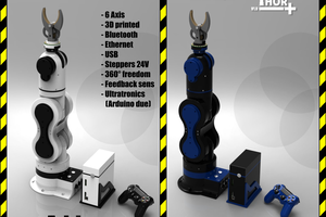
I found this cool robot on Hackaday (https://hackaday.io/project/12989-thor) that is bigger than my 3D printer so that is what drew me towards it.

The fact that it is big means that it forces me to think outside the box and face challenges to print it within reasonable time, keeps it functional, find workarounds when the printing fails, make it serviceable and makes it easier to extend.

I also get great advice and printable parts that fits my 3D printer from dannyvandenheuvel at
https://hackaday.io/project/16665-thor-robot-with-addons-and-gui

Thor has now also a team that I fully support: https://hackaday.io/project/12989-thor/log/51947-thors-community-is-now-onlin

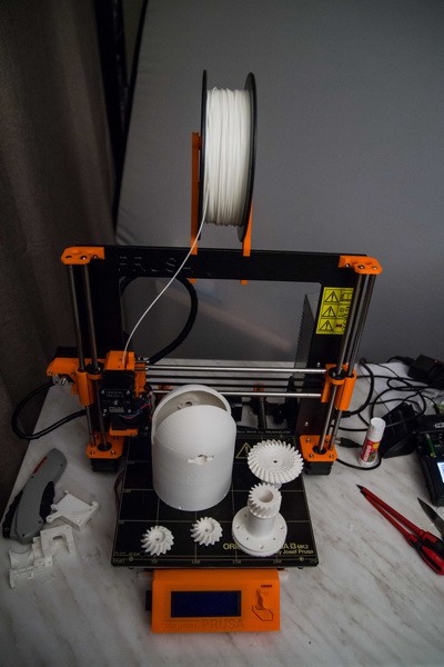
The Thor robot is going to be build on my Original Prusa i3 Mk2 printer. This printer can in theory print a 200x200x250 cm object but some part of the Thor is too big.
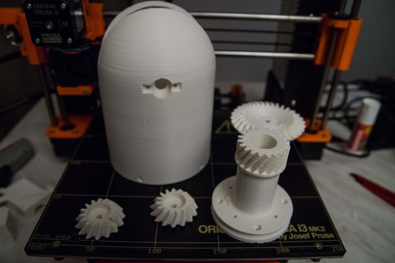
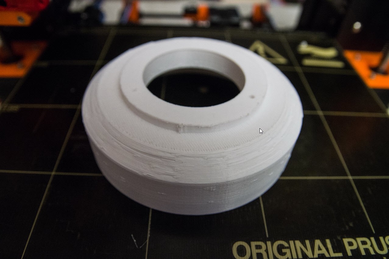
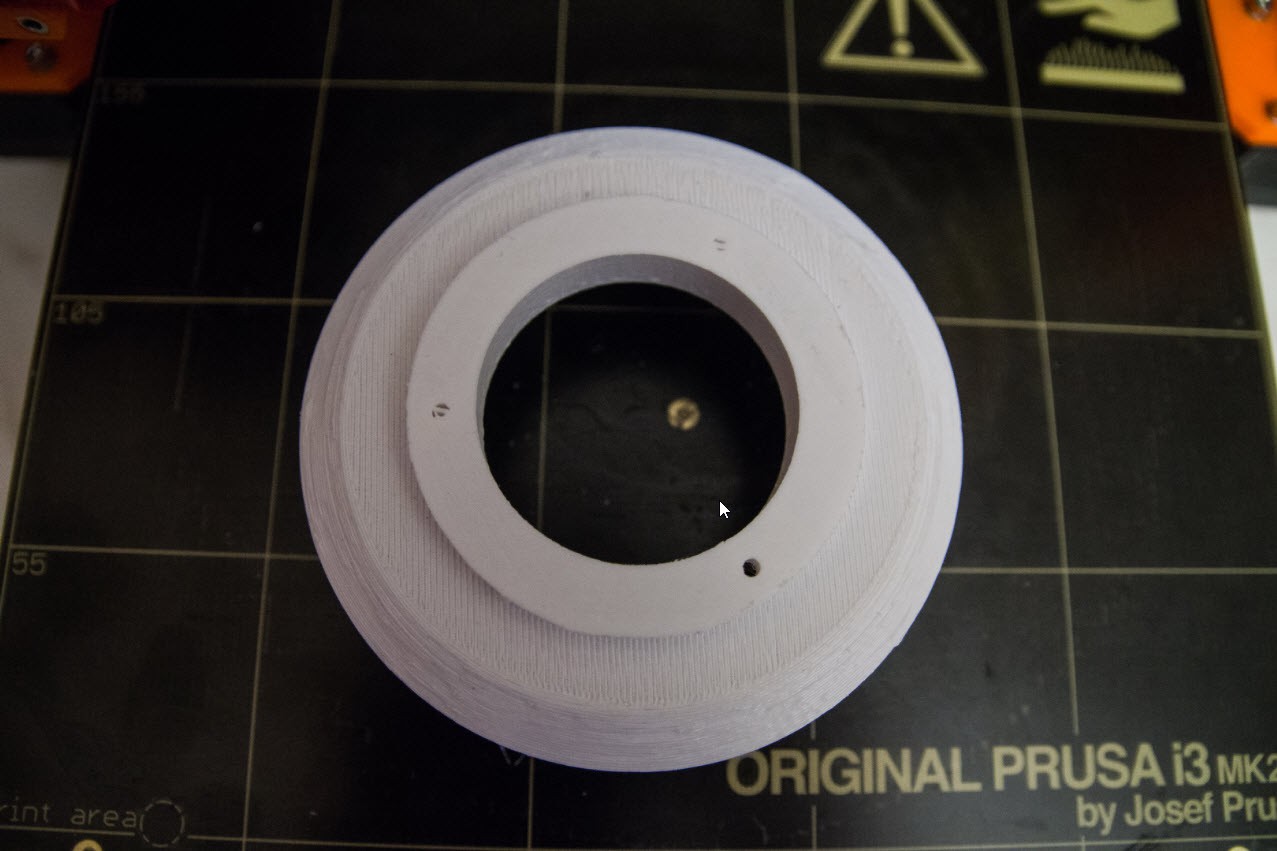
This big dome is called Art4Body currently using ABS filament with %20 infill, 4 top and bottom layers and 3 layers as outline (190 g of filament used) and prints in 11 hours. Art4Body is basically the upper arm of the robot.

10 hours into the print I ran into an issue with my extruder and it halted the print. Unable to continue I had to find a way to print the top part. Since I use Simplify3D I could estimate the Z layer, and move the model down. Simplify3D created the gcode to start from that layer on.

I finally glued the top and bottom part. Willit be structural strong? I have no idea, but when I press that dome thenI think an Elephant can stand on it.
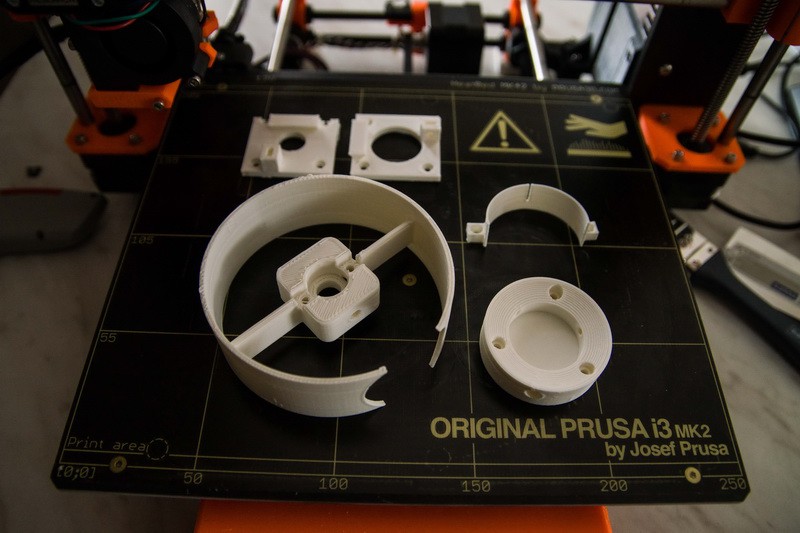
Printing more parts Art56CoverRing, Art32Optodisk, Art56Interface, Art56MotorHolderA and B. Infill 20% 0.3 layer height and took 3.5 hours. I think it is wise to use ABS plastic because some walls are very thin.

I do not have the motors, electronics, bearings,.....yet. Still figuring out where to order them from. The goal is to focus on the upper part first. The parts are smaller, and also more complex. It is a good way to learn to handle my 3D printer firs before getting in the bigger parts.

My Prusa i3 Mk2 has an issue between the contact of

the extruder temperature sensor and the electronics. The connector appears to have a bad contact making the temperature sensor jump during the print. I think I may need to solder that part.
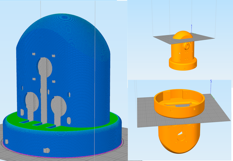
Art1Body is going to be a challenge to print. It originally needed 31 hours to print, but I could bring it down to 19 hours. The biggest reason why it takes so long is the support structure to hold the dome and the lower half flat panel that also needs support structures. Losing the support structure means winning 6 hours.

I am experimenting in Simplify3D to print it in 3 parts. The top halve, the mid section and the bottom part but upside down. I have chosen the top part to be printed above the openings that will have mechanical stress.
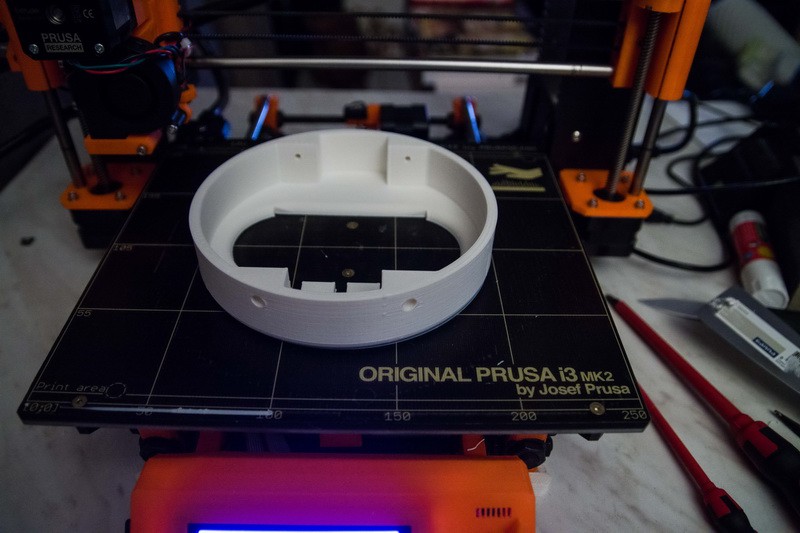
I finally printed the bottom part of the modified Art1Body. Note that it is upside down so I avoid support structures. This party is printed in 4h45 (vs 8h if it were to printed the upside way.)

Printing the mid section took me 8h45, and the top section that took 1h30. But when I removed the supports, I broke some thinner walls.
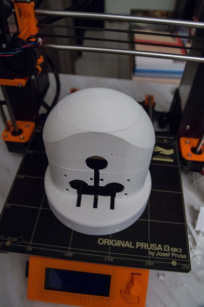
The gluing took challenges and I had to put 10 kg of boxes on top of it to hold it into place. I finally glued the dome on top. It is a Frankenstein model but it only took 13 hours of printing.

The gluing is surprisingly strong. Next will be gluing back the thinner walls.
  • 3 × ABS filament The original Thor project tells me that 4Kg of filament si required.
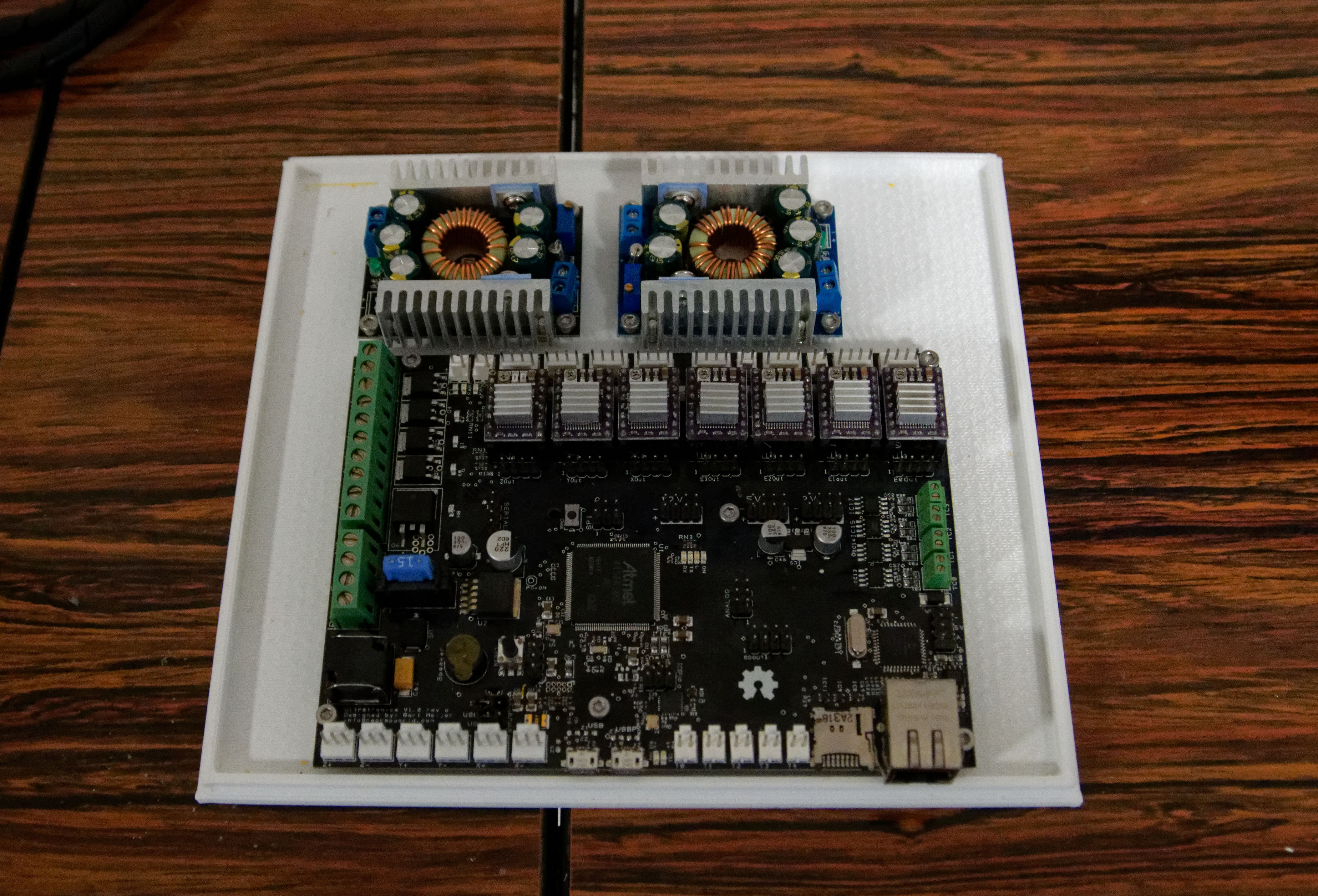
  • 1 × Ultratronics Pro v1.0 This board looks very similar to the popular Megatronics board, but it much more power due to the 32-bit Atmega SAM3X8E clocked at 84Mhz. (Expect €140)
  • 1 × SunPower SPS 100P-D2 100W Dual Output Enclosed Power Supply 5Vdc 10A Power supply to provice 5V 10A and 24V 4A. (Except €100)
  • 3 × Gear Ratio 5:1 Planetary Gearbox With Nema 17 Stepper Motor 17HS13-0404S-PG5 (DE208) 3 Geared motors to rotate the arm (expect €31 each)
  • 1 × Nema 17 Stepper Motor 2A 45Ncm(64oz.in) 17HS16-2004S1 Rotates the base (expects €10)

View all 7 components

  • Motor wiring now completed

    Olaf Baeyens01/01/2019 at 15:38 0 comments

    Took a lot of soldering buy all 7 motor connectors are now being soldered and connected to the motherboard.

    The connector at the right bottom is intended to provide 5V and 12V to the Thor robot to power additional electronics and power the cooling fans.

    On the left bottom I also provided a spare opening for a DB9 serial cable for additional communication for sensors inside the robot.

    Life gets easier for testing every motor independently during software development but also when it becomes part of the robot.

    The only missing part is the Nextion display that I reordered after damaging it with a reverse polarity.

  • Wrong polarity, blew up my Nexion display

    Olaf Baeyens12/29/2018 at 02:16 0 comments

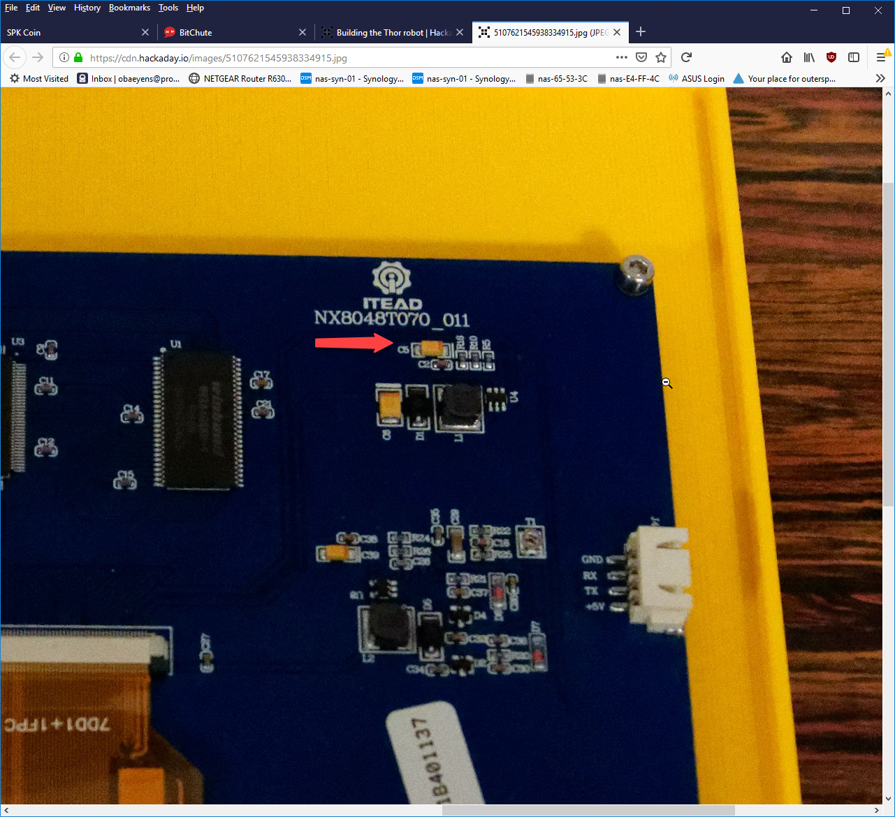
    Yesterday by accident I reversed the polarity of the +5V with the ground and I saw a flash. This capacitor blew up


    The capacitor is a 10µF, I tried to repair it but the display does not start up anymore not even when I try to upload new firmware. There is no other visual damage to be seen.

    I just ordered a new one to replace it.

    The rest of the electronics is still in good shape.

  • Designing the electronics box

    Olaf Baeyens12/27/2018 at 17:59 0 comments

    One year of standstill on the Thor project development because of other priorities in my life. But I have holidays so I continue where I left off.

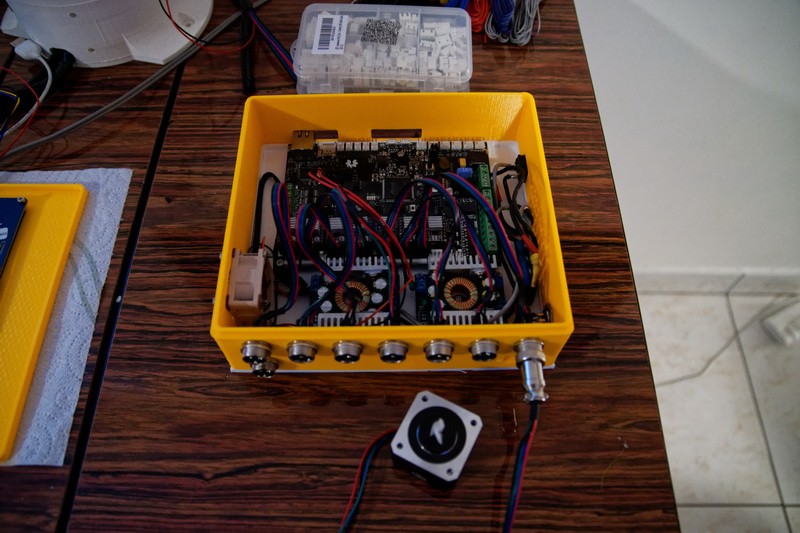
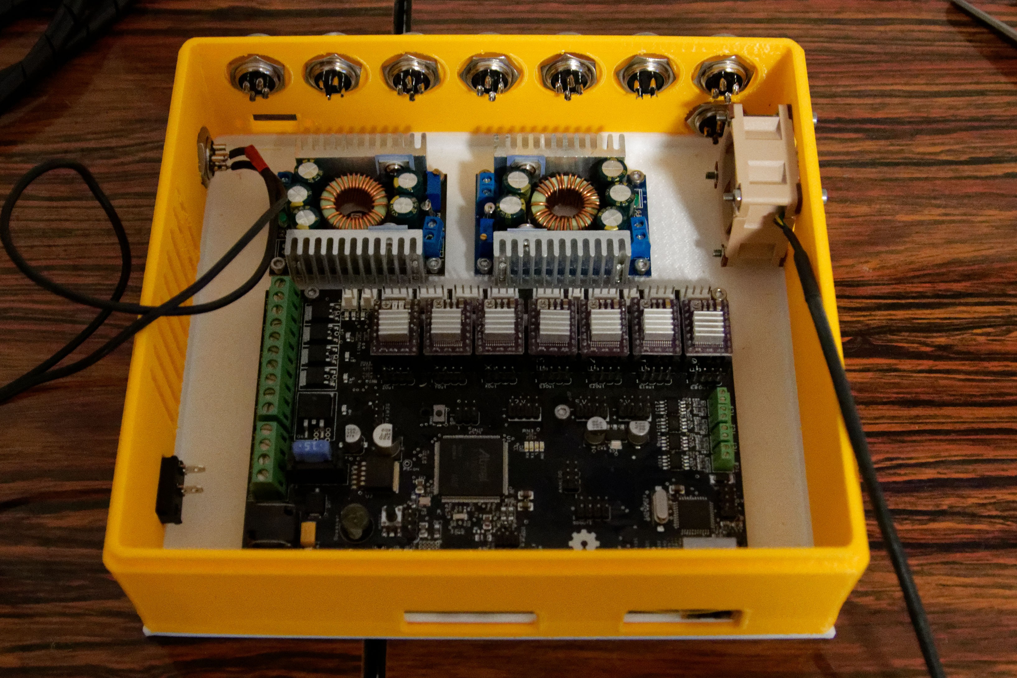
    The focus is on the electronics, now and since I had many sparks in my open test setup, it was time to contain it into an big box.

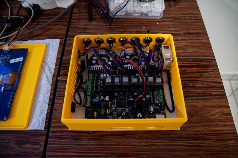
    The idea was the biggest box my printer could print 210x190 so I have space to change the internal electronics. The box consists of 3 different parts so I can alter them at will.

    For the controller I use 24V, but my cooling fans will be 12V and I also need 5V for the touch screen that draws a lot of current.

    So I decided to have 2 step down converters, one for 12V and one for 5V.  One additional 5V to 3.3V may be needed in the future but right now the mother board may give enough power.

    The side panels is printed as a separate 3d print. Again to play with different configurations.

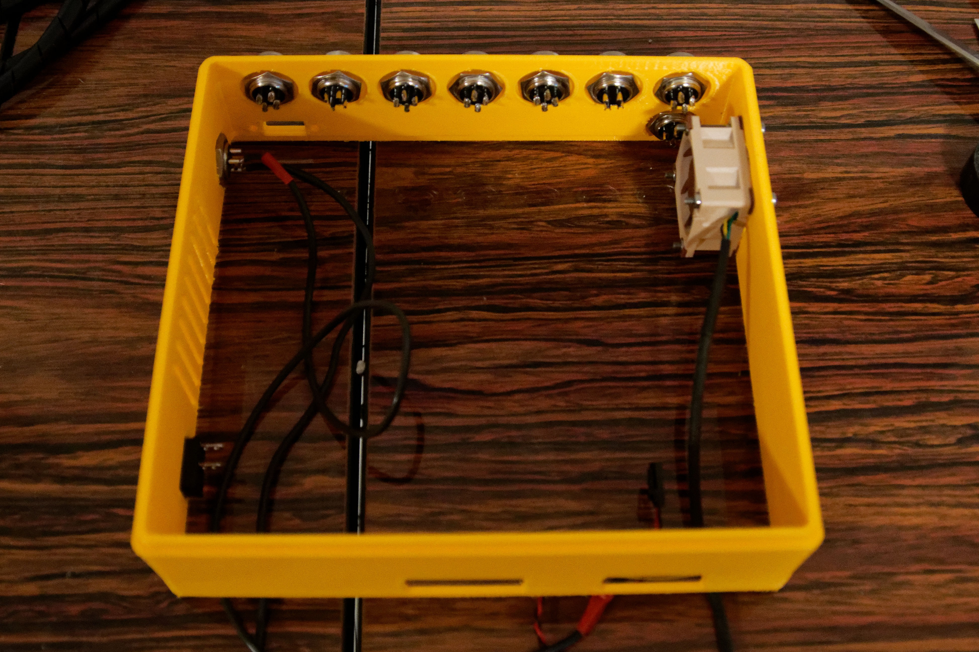
    I have a forced airflow using a silent ventilator to cool down the parts. Including the touch panel that also can become pretty warm. The ventilator is a Noctua 12V ventilator, because I tend to work at nights and the neighborhoods wants to sleep. The one in the one in the picture is 40x40x20  and only temporary. I had it laying around.

    The connectors at the top row are 7. One for each stepper motor. The intention is that I can pull each stepper-motor for testing. This way I can systematically test the software without the stepper motor to do real movements.

    One additional connector to provide 12V and 5V to the robot as additional supply. Could be used for the fans or additional electronics.

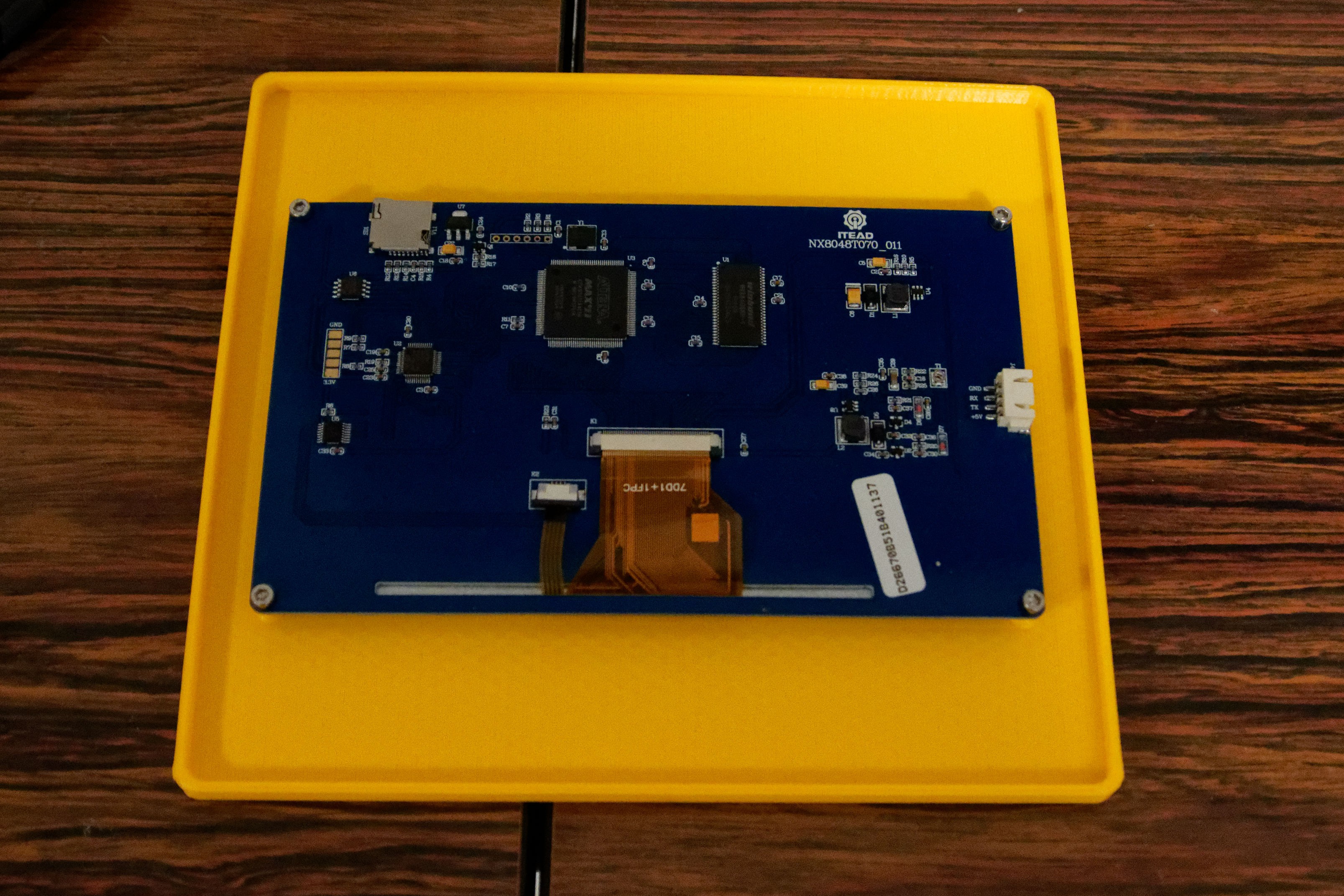
    The touch panel is at this moment mounted in a flat panel. For this setup this is enough, but could be reused as a  disconnected panel later in the design.  I already provided a RS232 opening in the side panels.

    View with the sidewall in place.

    Connector left is the incoming 24V from the external power supply.

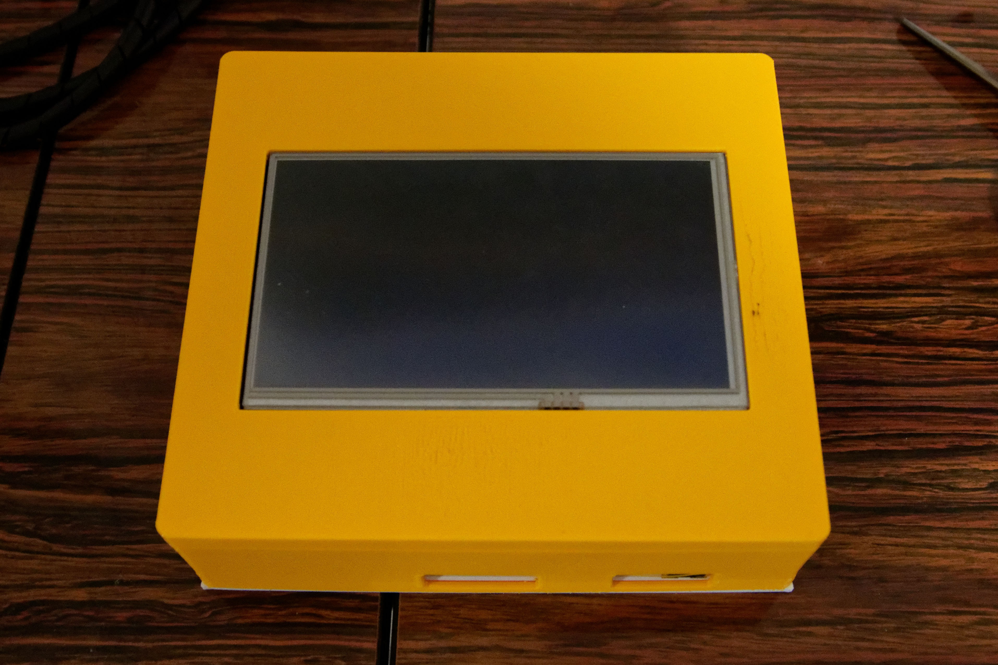
    Completed top view.

    The holes at the front are for the network connector and the 2 USB connectors.

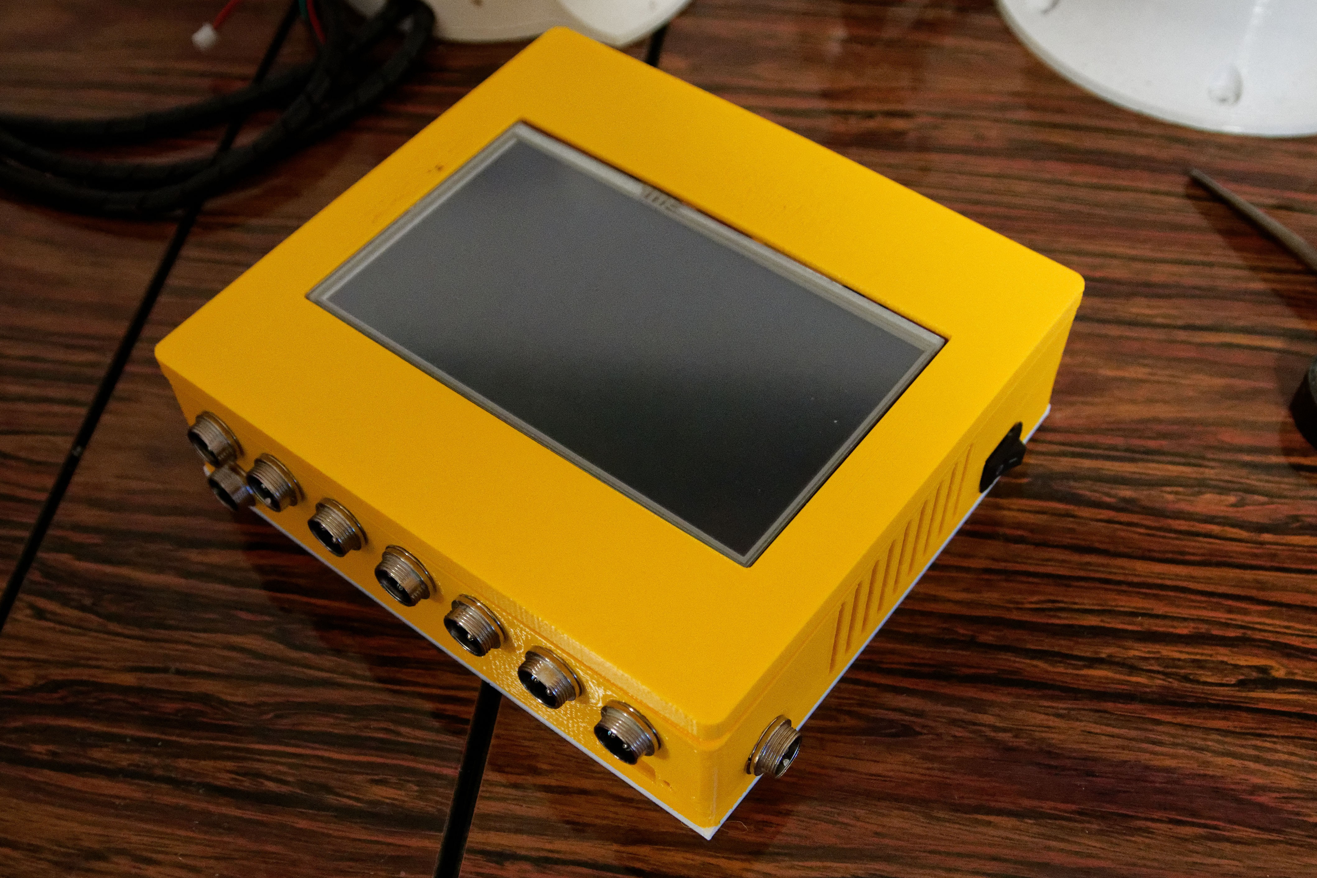
    Side view to show the connectors and also the power switch on the box. That power switch cuts off the incoming 24V, so the motor drops out instantly.
    Having a switch at the 220V mains does not act fast enough to cut the motor power. I need instant shut off-during development of the software.

  • Sepio's version of Thor upper parts

    Olaf Baeyens12/11/2017 at 00:39 3 comments

    Started to print the Thor upper part I have found created by Sepio: https://hackaday.io/project/26341-building-and-improving-the-thor-robot-arm/log/70087-day-18-redesign-of-art3-and-art4

    I needed to reprint the part because I need cooling, and it is a great way to test NGEN how it performs with bigger objects.

    I like Sepio's upper part, it looks easier to assemble and has a fan included to cool the upper part.

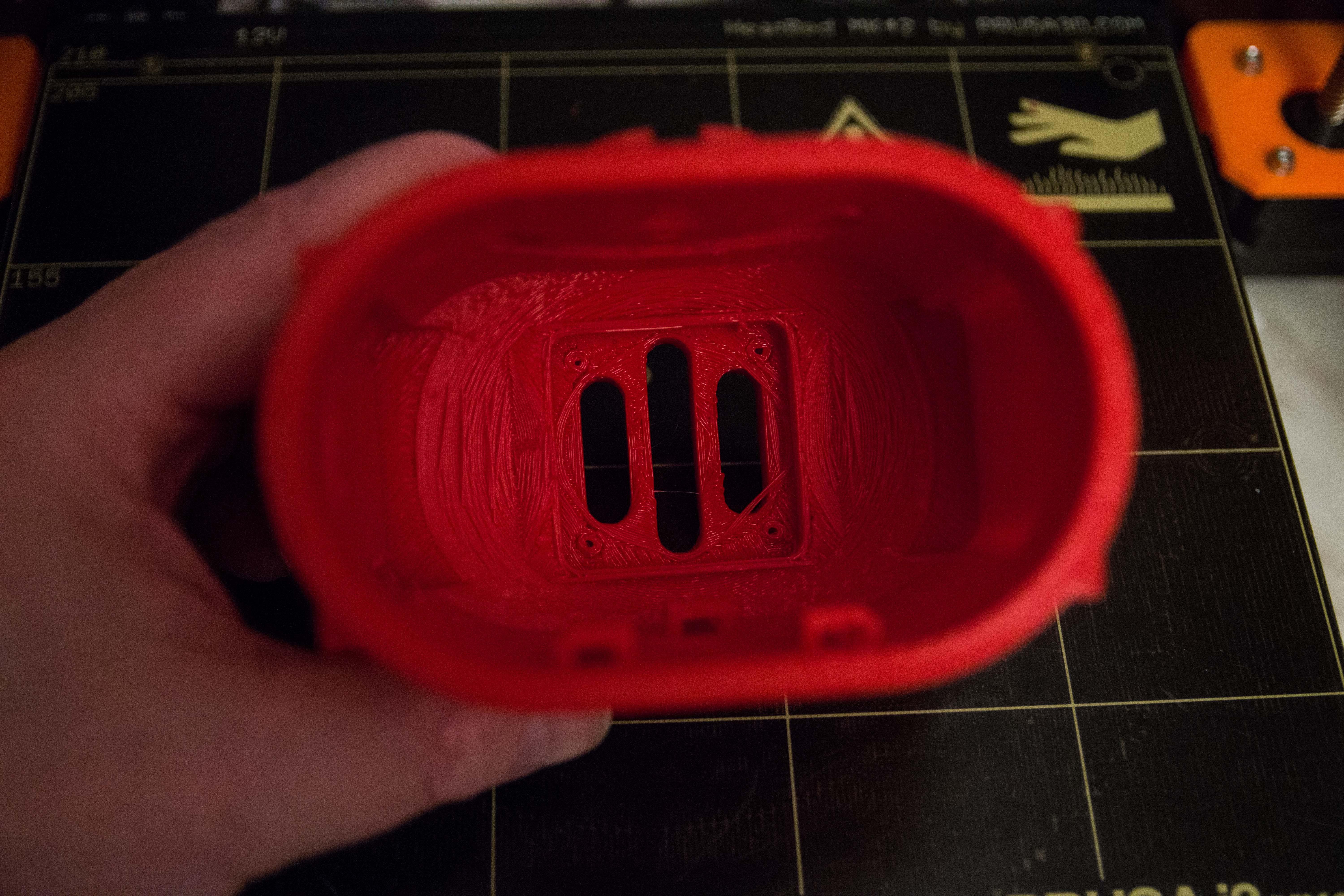
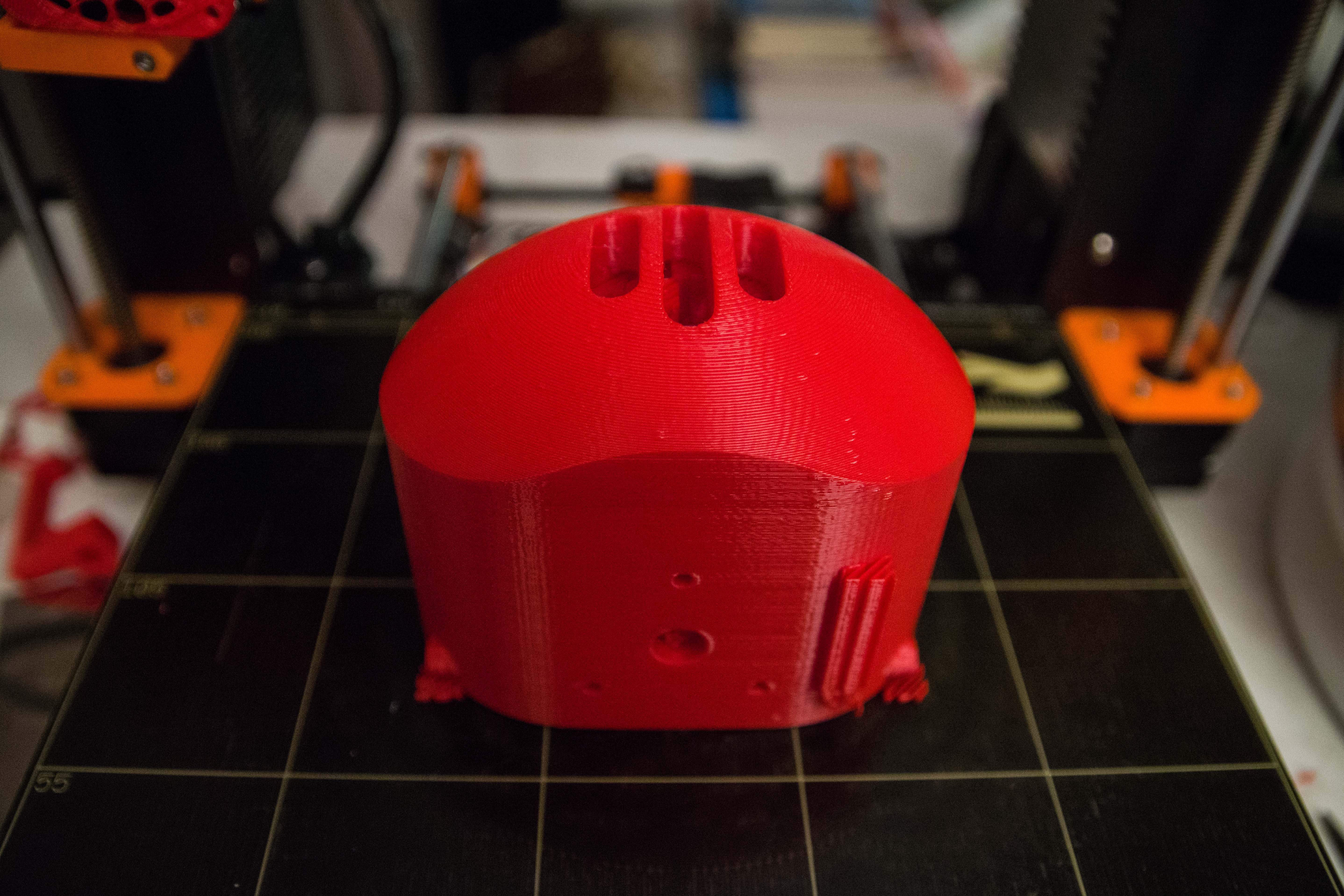
    The Art 3 lower body. 0.3 mm layer heights, Simplify3D estimated this a 7H job but it turned out to be 8H45. You can see the support structures that actually came off very easily.

    Inner part of Art 3 lower body.


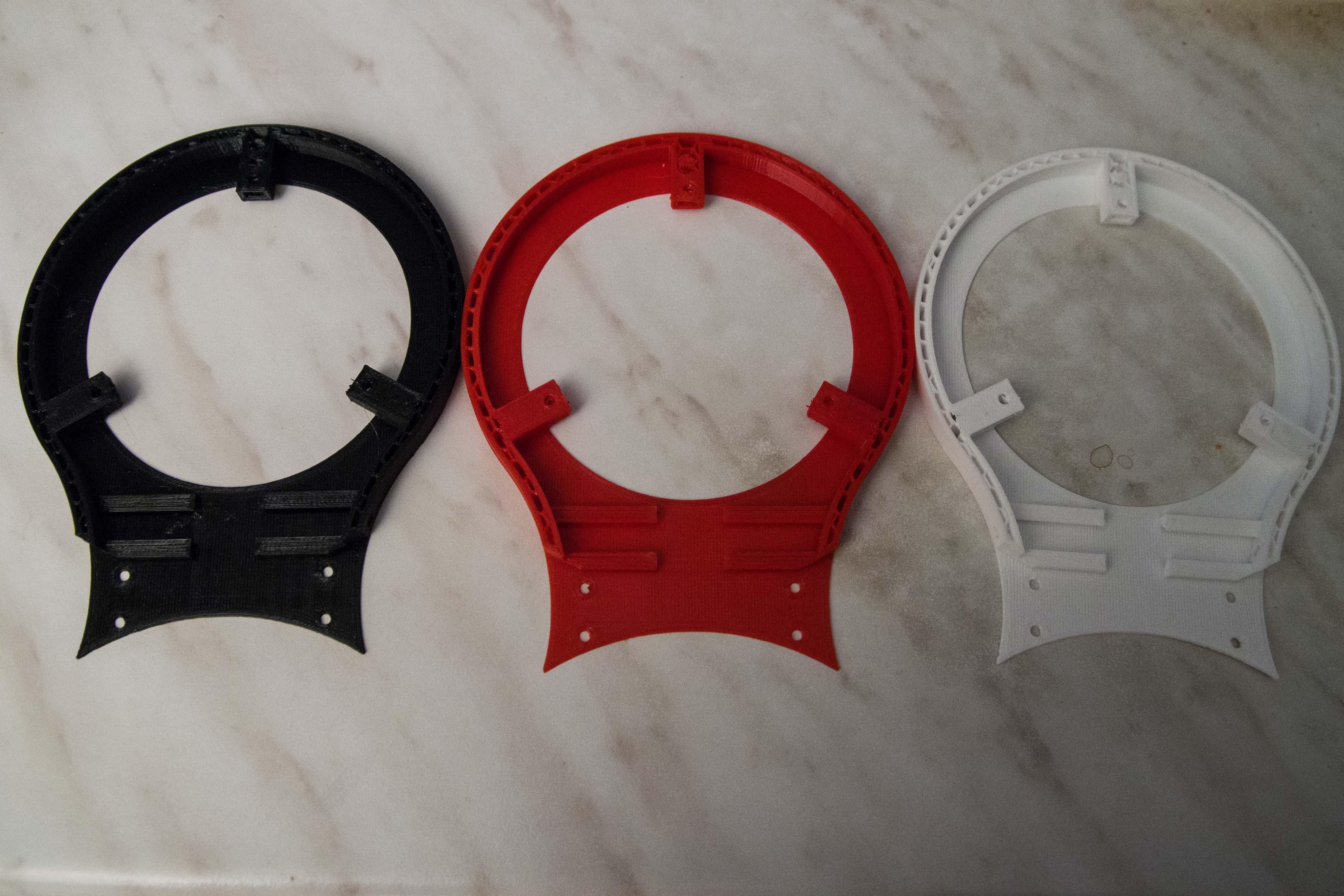
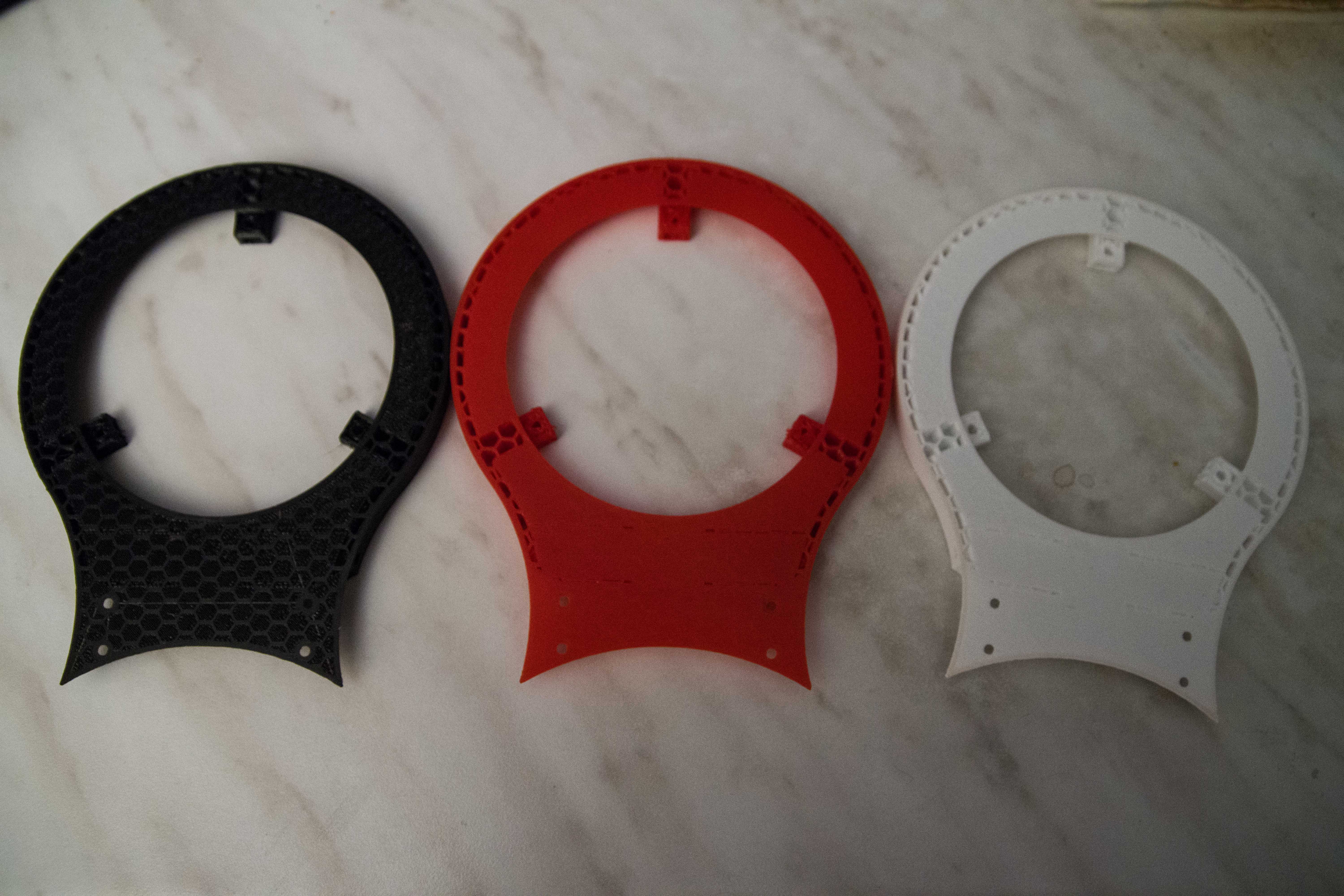
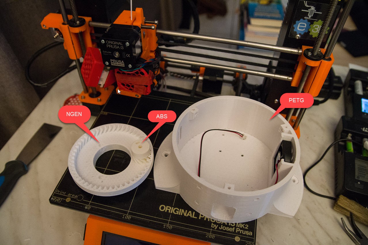
    The day before I tested 3 different materials I received on Friday.

    I started with the part that guaranteed failed every single time I used ABS.

    • Black = ColorFabb_HT (€ 45/700 gr,)
    • Red = ColorFabb_XT (€ 40/700 gr)
    • White = ColroFabb NGEN (€ 35/700 gr)

    All 3 jobs are 2 hours printing.

    Top parts

    Bottom parts

    That test concluded me to go for NGEN when I print parts for Thor.

  • Some fillament tests

    Olaf Baeyens12/04/2017 at 21:45 1 comment

    Not directly related to the Thor project but I know that some people are interested.

    I have an Original Prusa MK2 (MK2/S upgraded now)

    I always had big issues with warping when I use ABS (ICE) filament when printing the Thor robot.

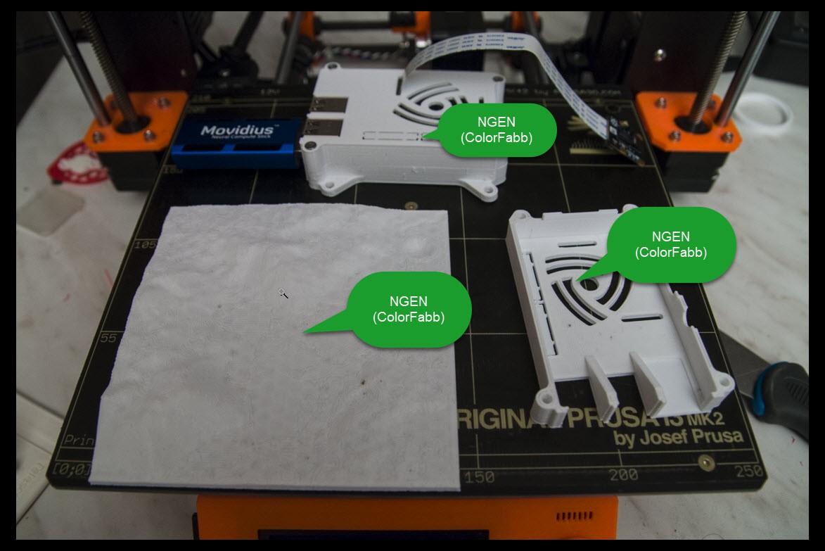
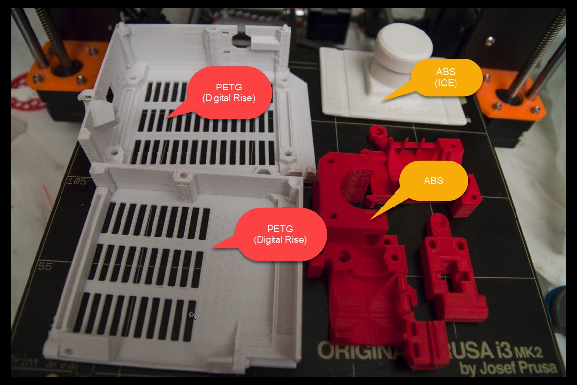
    Here are some samples with different materials.

    Top is my Movidius Raspberry Pi 3 with camera intended to experiment with Neural networks.

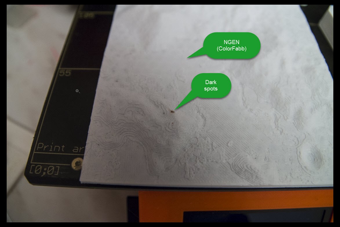
    Bottom left is a Apollo 15 landing site I used as an experiment to testprint my Original prusa i3 MK2/S upgrade. I originally used 2 top layers which worked great with ABS but with NGEN it definitely needs 4 top layers.

    Detail part of the Apollo 15 landing site. Layer height is 0.2 mm NGEN, and I did notice these dark spots I cannot explain. I never saw them when using ABS or PETG.

    Parts that I printed for the MK2 to MK2/S upgrade of my printer. I did not install them yet.

    The top part right is a test print  with ABS (ICE) because I was wondering if the printer upgrade made thee ABS print better, but I still had the warping issue. However the red ABS (also ICE) made a perfect print.

    Also you don't see these mysterious dark spots I had with NGEN.

  • ART1BOT in NGEN filement

    Olaf Baeyens11/11/2017 at 19:53 3 comments

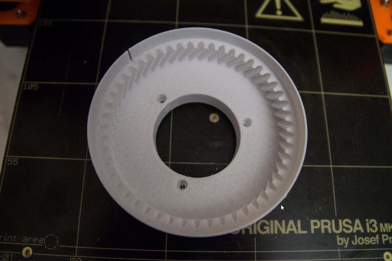
    Test of ART1BOT this time printed in NGEN filament.

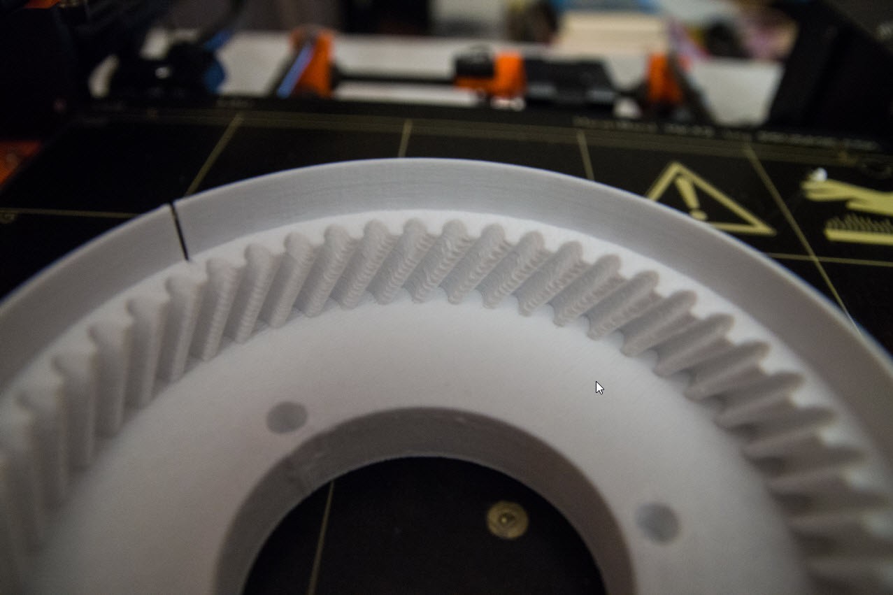
    It printed without any hiccups on my 3D printer nor warping. It feels very solid and the details are pretty good.

    Detail of the cogs 

    The rim is almost not bendable, and will splinter when pressed to hard.

    Bottom part (actually this is the upper part in the Thor robot). You can see that support structures left some fragments behind. The object does have sharp edges, something I did no have when using ABS. But these sharp edges are easier to get rid of wit sand paper. Easier than ABS.

  • Upgrade my printer/ NGEN filament test

    Olaf Baeyens11/11/2017 at 15:37 0 comments

    Because the Thor robot has multiple long duration 3D prints I tried to reduce the noise of the printer because some prints goes into the night. I don't think my neighbors can hear it but I prefer to prevent it is I can.

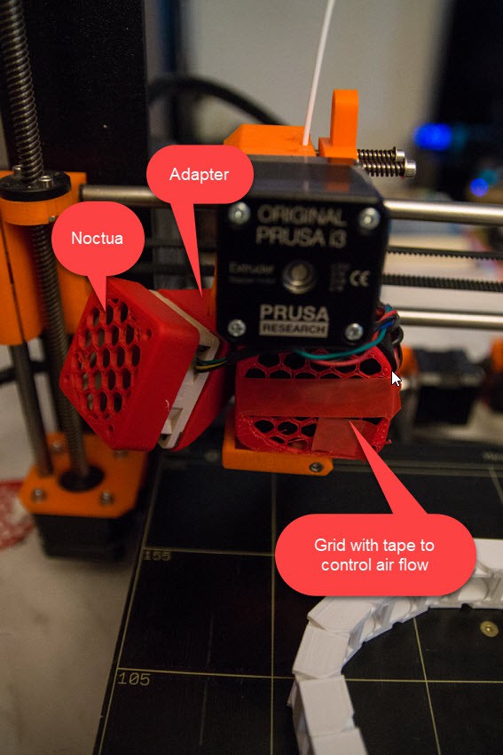
    So  upgraded my Original Prusa MK2 with a Noctua fan that needs an adapter.

    The adapter I used is : https://www.thingiverse.com/thing:2076234

    The fan used is http://noctua.at/en/nf-a4x20-pwm

    The NF-A4x20 is 20 mm thick and I paid 14 euros.  It is really that silent.

    You also see that on the right I have a 3D printed fan cover that I can control the air flow with by adding or removing tape (even during printing). The fan itself caused in many cases a Termal Runnaway and ruined the print.


    The Prussa MK2 printer has big issues with warping when I print with ABS.

    Last time I tried PETG, which is more flexible than ABS but also more droopy. The filament support structures are hard to remove.

    Danny pointed me to ColorFabb NGEN, more expensive but I gave it a try.

    http://www.omd3d.com/omd3deshop/co-polyesters/63-ngen.html

    (Remark, the site seems to have a bug in its javascript. You have to press the browser refresh page every time you selected something in Firefox)

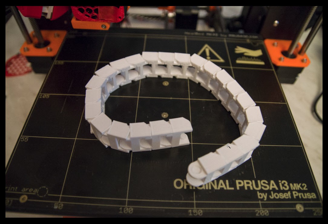
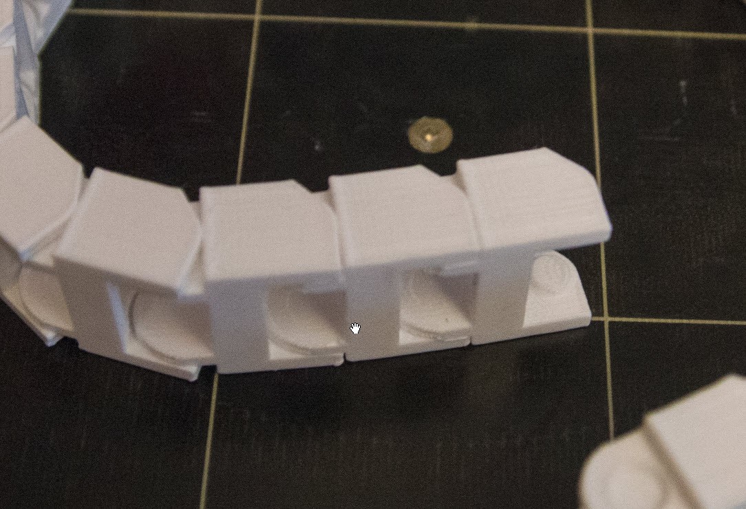
    (Assembled cable train)
    First print was parts to have a cable train.
    With ABS they all came lose of the bed during printing. But with NGEN they did stick and the print worked out nicely. I printed at standard 2400 mm/min and even 4200 mm/min. 

    The first things you notice is that the NGEN plastic is as hard as PLA. So far it seems not to break as fast as PLA, but it does break when you bend it too far. 

    Detail of the cable train.


    A comparison of Thor printed parts in different materials.

    I had to break of the left part (ART1BOT) printing job because it was well into the night and it took longer than what Simplify3D predicted (I think the Prusa printer moved slower than 4200 mm/min)

    I am redoing this job at this moment since this part had a sensitive thin wall part that easily broke off in ABS.

    I tried to print this part with CarbonFil but my printer stuck its head several times on the parts and I got an offset error and a failed print. I think this NGEN can do the same thing as the CarbonFil. 

  • The art of debugging through Debug LED

    Olaf Baeyens10/28/2017 at 19:17 1 comment

    Last week I decided to restart the Thor software design, this time built up to be more professional. With Professional I mean, adding comments, structured naming conventions, prepare it for full blown professional design.

    As I was commenting the code I ended up at my Debug LED part and started to wonder about debugging the software.

    The initial design was actually programmed for an Arduino Nano. I did not have a logic analyzer yet and I wanted to test the concepts of the interrupt based pulses. I used the Debug LED to visually see if the code actually worked. I could slow the step motor pulse to any speed I wanted even step per step.

    The Arduino Nano is so easy to hook up to your PC, no wiring, no real mechanical parts and it forced you to develop code wiring an even more constraint space.


    Months later, I had issues with the compiled code. I had code that would perfectly work on a Windows PC but for some reason it failed. So I extended the debug LED code to blink at setup(). I used the debug LED blinks to find where the code stopped functioning.

    I can only conclude that it had to be some compiler bug. Rewriting my code made it goes away. But that blinking LED was vital for finding a workable solution.

    The Debug LED was of no more use... or so I thought....


    Yesterday I found that debug LED code, decided to clean it up even though I had no use for it anymore. Went to bed and suddenly start to realize that this debug LED is very vital for my Thor controller!

    This single tiny LED is always on the Arduino controller, it never fails and can give vital feedback of the state of the software even if there is no display connected to it!

    It can display the initialization stage, it can display the diagnostic stage, it can display the running stage... Just by blinking.

    The key to all this is how you blink.

    Ideas are:

    • Initialization stage: blink when it goes to the next stage. Since every initialization stage will be different in duration, the debug LED pattern will flash in a predictable pattern.
    • Running could be a regular repetitive blinking.
    • Critical error could be a fast blinking state, or all on or off when the software crashed.
    • Starting an operation could be a 1 second LED on followed by a second off as a warning that something is happening.
    • Short blinks could indicate a command received from the display.
    • Repetitive morse code could tell you an error code.

    All this means is that my debug LED code will be extended dramatically.

  • ​Restarting the Thor software project from scratch.

    Olaf Baeyens10/22/2017 at 23:21 2 comments

    Restarting the Thor software project from scratch. This time with the intention to make it publishable over time.

    The software will be built from the ground up, not relying on libraries. The whole point of all this is to learn to develop robotics code from scratch.

    It is written in C++ (Visual Studio 2015) with a plugin called Visual Micro that compiles the C++ code to the Arduino Due.

    I already have the these parts described in my blog posts:

    • Arduino Duo - Ultratronics v1.0 pro port mapping to the correct stepper motors.
    • Enable, direction and stepper driver control with the purpose to move 7 motors simultaneously per step.
    • Interrupt driven timer that works on the Arduino Due (this is different than an Arduino Uno/Mega)
    • Nextion button press reaction to be modified in a more elegant design needed for the Thor control.

    For me this is my little private project. I prefer to keep developing this at my own pace and on my own. I already work in teams professionally, this one I want to call my own. :-)

  • Redesigning Nextion HMI library

    Olaf Baeyens10/02/2017 at 15:56 0 comments

    The Nextion HMI display library is good but for my Thor implementation too generic and not good enough for lots of controls, speed and reliability.

    So I have chosen to redesign the library so in the end I have a more compact code and optimal (communication) for the Thor robot.

    This code will evolve as it is being designed.


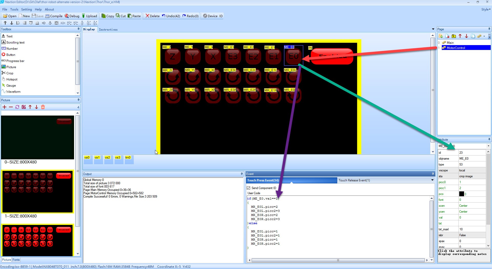
    First the Nextion HMI editor project

    We are designing a screen that have 7 enable buttons and beneath these buttons we have 2 rotation buttons. The original Nextion library code would have too many callbacks and hacks for what I have in mind.

    I want to make sure that the connection Thor - Nextion HMI display is being monitored and that the Thor main controller can detect a HMI display that is giving wrong commands or unresponsive.

    I also want the Thor robot controller library to be created more intelligently.

    This screen show that for Page 1, we have a dual state button that will be programmed to enable and disable the rotating buttons below if it si active or not. This code demonstrates that we copy the bitmap under bitmap 2/3 (green/red active button) or 1 (disabled button)

    This code runs on the HMI display only and does not burden the  Thor robot controller with too much communication.

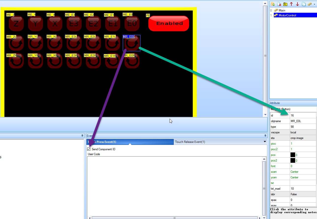
    The button has the "Send Component ID"  checked for both the Touch Press event and the Touch Release event. This will send a serial command to the Thor controller when pressed and depressed.

    (If you look at this example, I have shortened the names and there is a reason for this. When I read in properties for this control from the Thor robot controller, the complete name is being transmitted which means longer transmission times and responses.

    The button "Send Component ID" is seen below

    The "Send Component ID" is a start byte indicating that we have a "Button" command, then followed with a page ID, the Control ID and a value 0 if it is depressed or 1 if it is pressed. It completes with 2x255 bytes marking the end of a command.

    No properties of that control is being transmitted, that is not part of the current code I want to redesign yet.

    This primary goal is to send make the Thor robot step the motor in a left or right direction and immediately stops when I release the button.

    The Nextion Library has a call back method that you attach to a Pop (release button) and Push (press button) event.  I want to have only one callback for starting.

    Which is defined below:

    typedef void(*TouchEventButton)(byte page, byte button, byte pressed);

     The callback should be used as in example below:

    void ButtonPress_Callback(byte page, byte button, byte pressed) {
    	if (page == 1) {
                    // Check on button MR_E0L (Motor Rotate E0 channel Left direction)
    		if (button == MR_E0L) {
                            // I always check on value 0, only 0 = false anything else is true
    			if (pressed != 0) {
    				digitalWrite(LED_BUILTIN, HIGH);
    			}
    			else {
    				digitalWrite(LED_BUILTIN, LOW);
    			}
    		}
    	}
    } 

    This callback can now be much easier to extend, but also used as a very basic.

    The callback should be processed in the Arduino Loop() method.

    void loop() {
    	// process incoming Nextion button presses
    	display_loop(ButtonPress_Callback);
    }

    Initialization is done like this:

    Choose the COM1 channel (you have Serial, Serial1, Serial 2, Serial 3)

    #define nexSerial Serial1

    Initialize the display, and set it to page "0"

    bool display_init(void) {
    	nexSerial.begin(9600);
    	displaySendCommand("");
    	displaySendCommand("bkcmd=1");
    	bool ret1 = displayRetCommandFinished(1000);
    	displaySendCommand("page 0");
    	bool ret2 = displayRetCommandFinished(1000);
    	return ret1 && ret2;
    }
    void displaySendCommand(const char* cmd) {
    	clear_buffer();
    	// Send command 
    	nexSerial.print(cmd);
    	nexSerial.write(0xFF);
    	nexSerial.write(0xFF);
    	nexSerial.write(0xFF);
    }
    void clear_buffer() {
    	//...
    Read more »

View all 74 project logs

Enjoy this project?

Share

Discussions

Kung Fat wrote 12/29/2016 at 17:15 point

This is both really impressive because of the skill of the printing and somewhat nail-biting for me to see the gears and so on simply being printed- I think it's going to be a lot better, eventually, to print the body/case of the robot and the suitable structures in it to be able to mount standard off-the-shelf hardware like bearings, gears, and machined parts that are stress-critical.

All of  this is impressive, keep it up.

  Are you sure? yes | no

Olaf Baeyens wrote 12/29/2016 at 17:34 point

Thanks

  Are you sure? yes | no

Alex Martin wrote 12/23/2016 at 04:46 point

Your printing skill is admirable!

  Are you sure? yes | no

Olaf Baeyens wrote 12/23/2016 at 18:00 point

Lots of failed prints! It is surprisingly hard to print successfully. But at a certain point your printer has been finetuned where printing eventually starts to become predicable.

This Thor project already took up 134 hours of printing time.

  Are you sure? yes | no

Olaf Baeyens wrote 10/23/2016 at 20:29 point

I looked at the parts list of Thor and I notice way way too many different types of screws. It is not a problem for seasoned robot builders but it is a problem when you start fresh building robots and have to find the screws to order. 

I think 3 different lengths would be nice that is used consistent.

I also appear to need different lengths of rods. This is harder to find, so for the first trial I may have to resort to 3D printed.

  Are you sure? yes | no

Olaf Baeyens wrote 10/23/2016 at 20:11 point

I knew I was missing something, the bottom of the upper arm. 

It appears to be the same objects as Art1Body. That is a touch job since I can't make it below 19 hours of printing.  Now I have to do it twice.  

The support structures to print it uses up 6 hours. Getting rid of these support structures by redesigning might solve this. Printing the bottom part upside down and the top normal and then find a way to glue them together may get rid of the support structures. But I that is in a next stage when I have learned how to design my own drawing.

  Are you sure? yes | no

Olaf Baeyens wrote 10/22/2016 at 12:59 point

Printing more parts Art56CoverRing, Art32Optodisk, Art56Interface, Art56MotorHolderA and B.  Infill 20% 0.3 layer height and took 3.5 hours. I think it is wise to use ABS plastic because some walls are very thin.

I do not have the motors, electronics, bearings,.....yet. Still figuring out where to order them from. The goal is to focus on the upper part first. The parts are smaller, and also more complex. It is a good way to learn to handle my 3D printer firs before getting in the bigger parts.

My Prusa i3 Mk2 has an issue between the contact of the extruder temperature sensor and the electronics. The connector appears to have a bad contact making the temperature sensor jump during the print. I think I may need to solder that part.

  Are you sure? yes | no

Olaf Baeyens wrote 10/19/2016 at 20:48 point

This big dome is called Art4Body currently using ABS filament with %20 infill, 4 top and bottom layers and 3 layers as outline (190 g of filament used) and prints in 11 hours. Art4Body is basically the upper arm of the robot.

10 hours into the print I ran into an issue with my extruder and it halted the print. Unable to continue I had to find a way to print the top part. Since I use Simplify3D I could estimate the Z layer, and move the model down. Simplify3D created the gcode to start from that layer on.

I finally glued the top and bottom part. Will it be structural strong? I have no idea, but when I press that dome then I think an Elephant can stand on it.

  Are you sure? yes | no

Similar Projects

Does this project spark your interest?

Become a member to follow this project and never miss any updates