One year of standstill on the Thor project development because of other priorities in my life. But I have holidays so I continue where I left off.
The focus is on the electronics, now and since I had many sparks in my open test setup, it was time to contain it into an big box.
The idea was the biggest box my printer could print 210x190 so I have space to change the internal electronics. The box consists of 3 different parts so I can alter them at will.
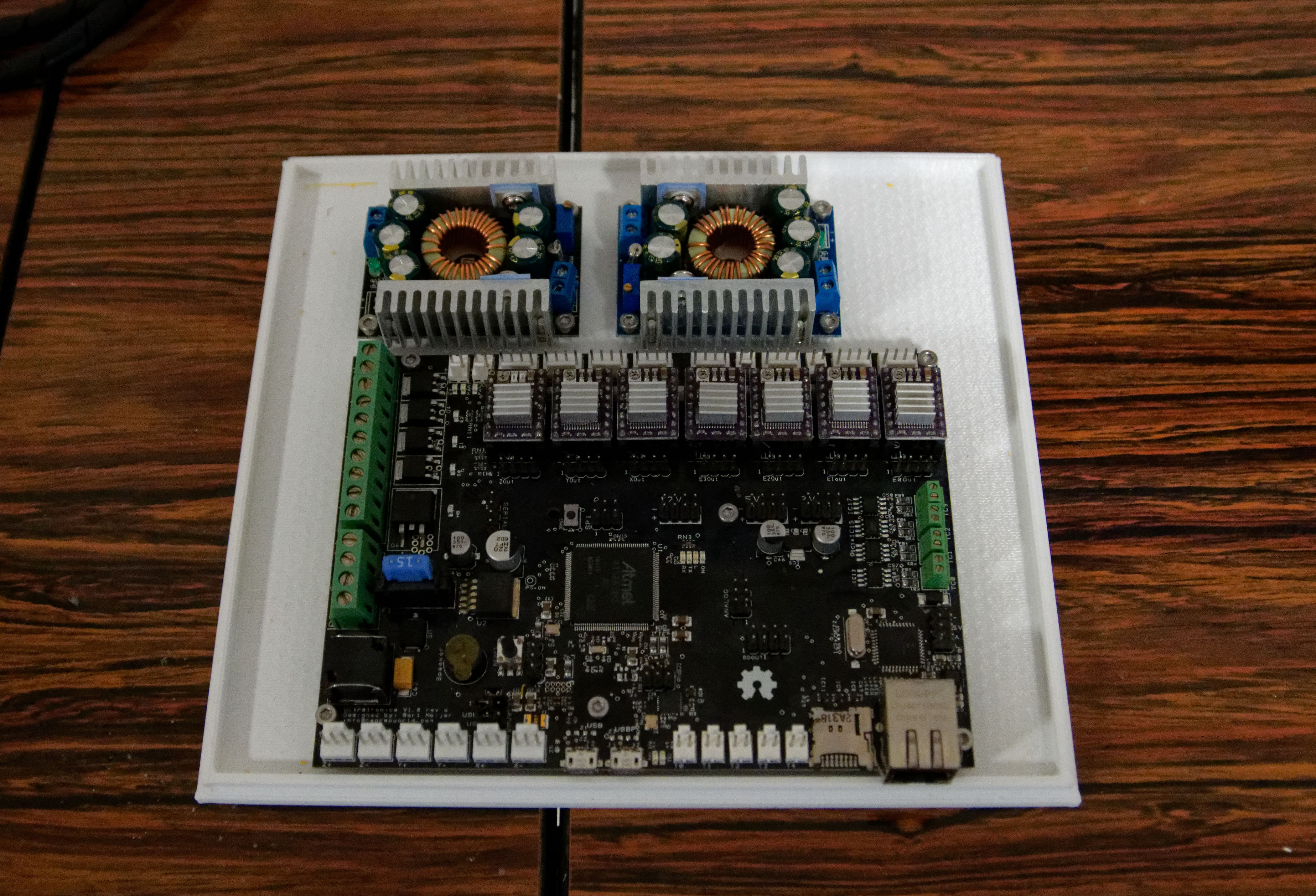
For the controller I use 24V, but my cooling fans will be 12V and I also need 5V for the touch screen that draws a lot of current.
So I decided to have 2 step down converters, one for 12V and one for 5V. One additional 5V to 3.3V may be needed in the future but right now the mother board may give enough power.
The side panels is printed as a separate 3d print. Again to play with different configurations.
I have a forced airflow using a silent ventilator to cool down the parts. Including the touch panel that also can become pretty warm. The ventilator is a Noctua 12V ventilator, because I tend to work at nights and the neighborhoods wants to sleep. The one in the one in the picture is 40x40x20 and only temporary. I had it laying around.
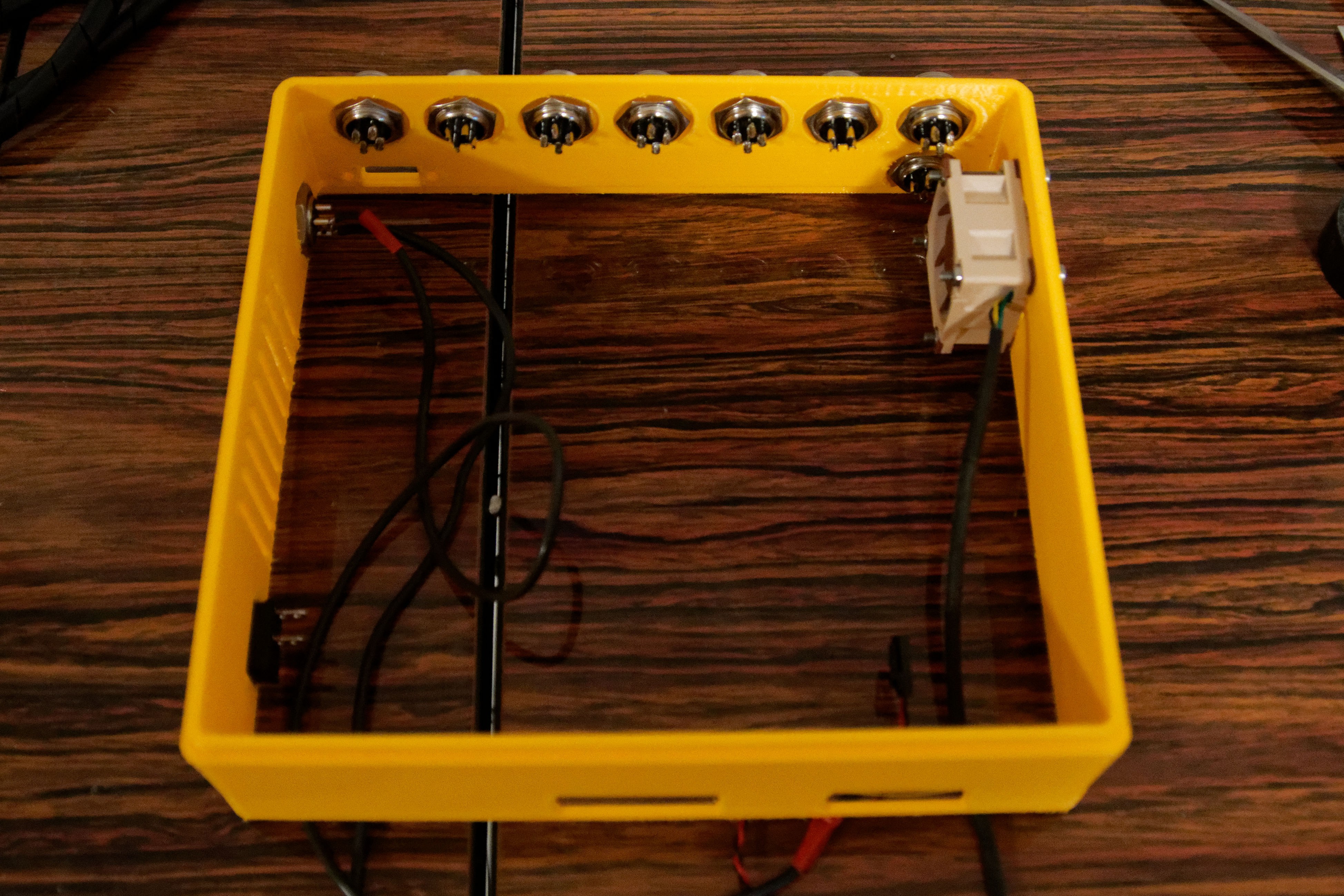
The connectors at the top row are 7. One for each stepper motor. The intention is that I can pull each stepper-motor for testing. This way I can systematically test the software without the stepper motor to do real movements.
One additional connector to provide 12V and 5V to the robot as additional supply. Could be used for the fans or additional electronics.
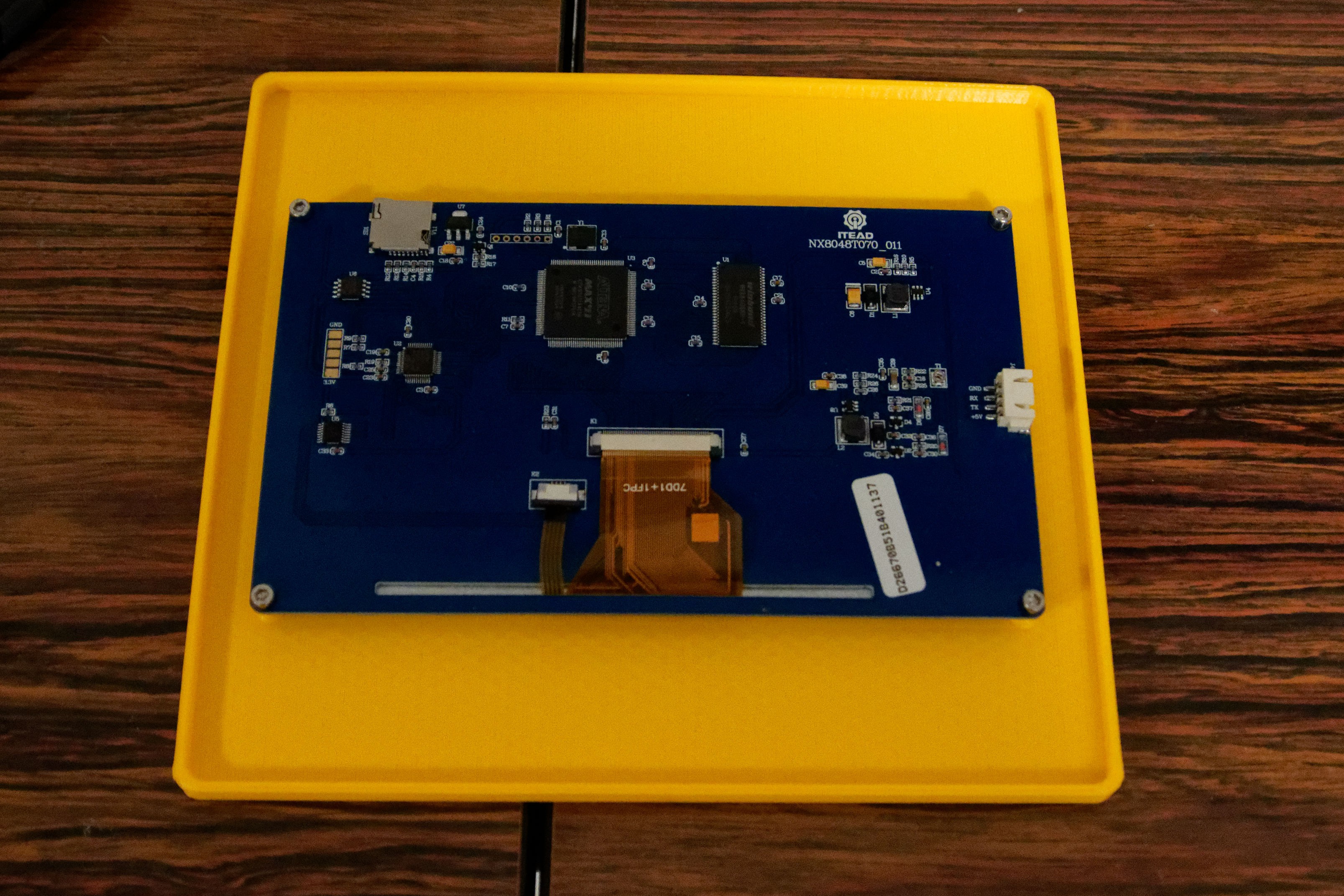
The touch panel is at this moment mounted in a flat panel. For this setup this is enough, but could be reused as a disconnected panel later in the design. I already provided a RS232 opening in the side panels.
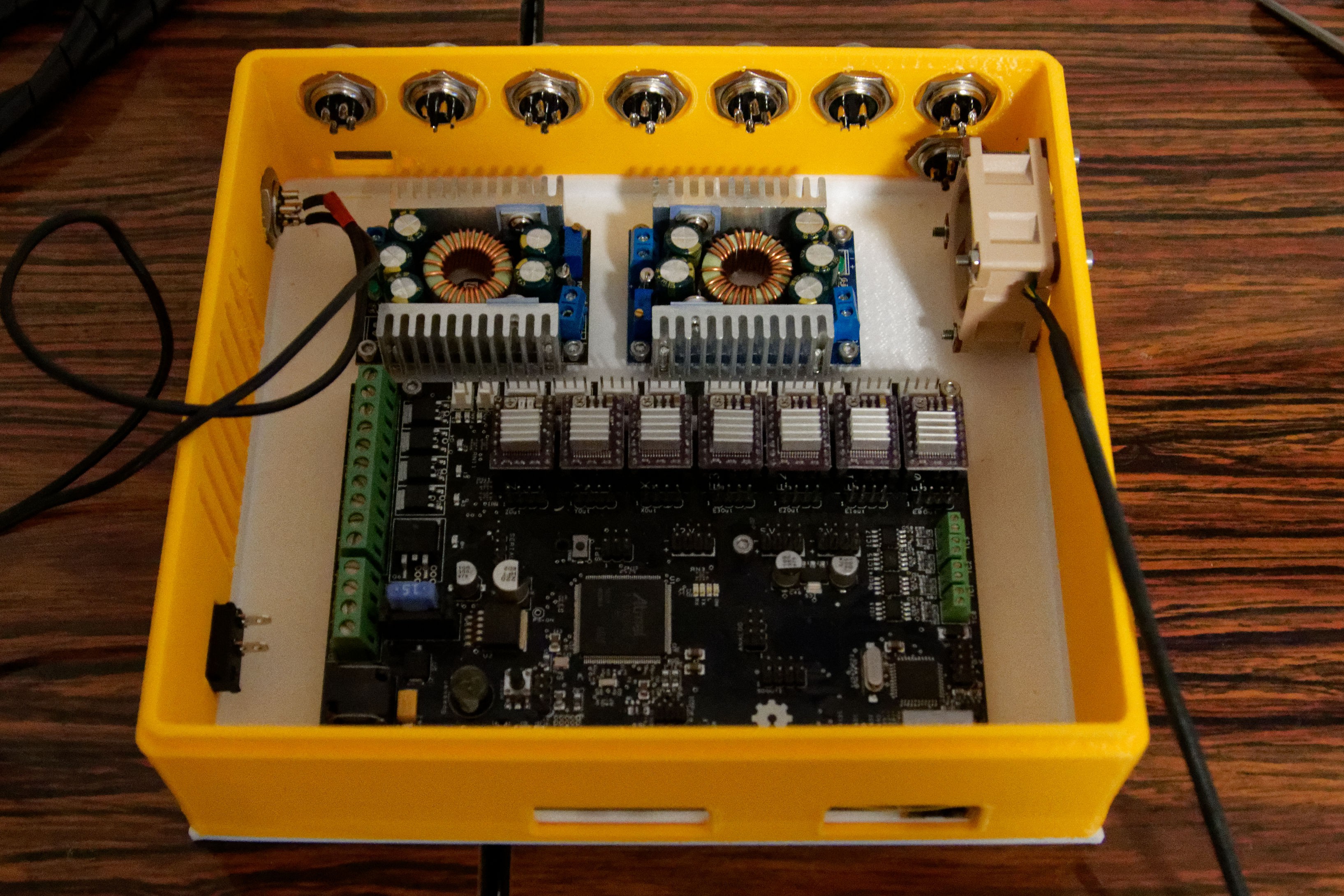
View with the sidewall in place.
Connector left is the incoming 24V from the external power supply.
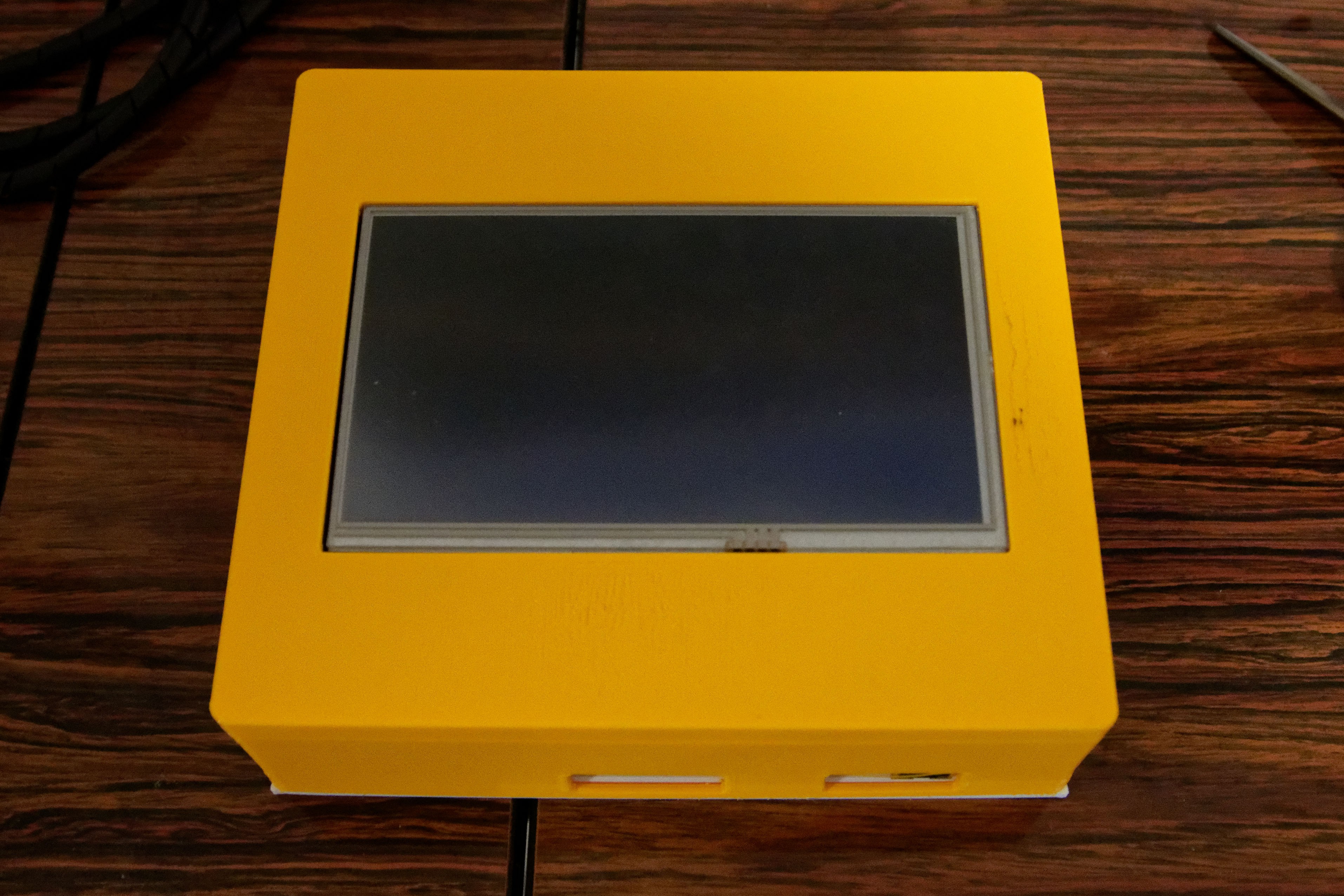
Completed top view.
The holes at the front are for the network connector and the 2 USB connectors.
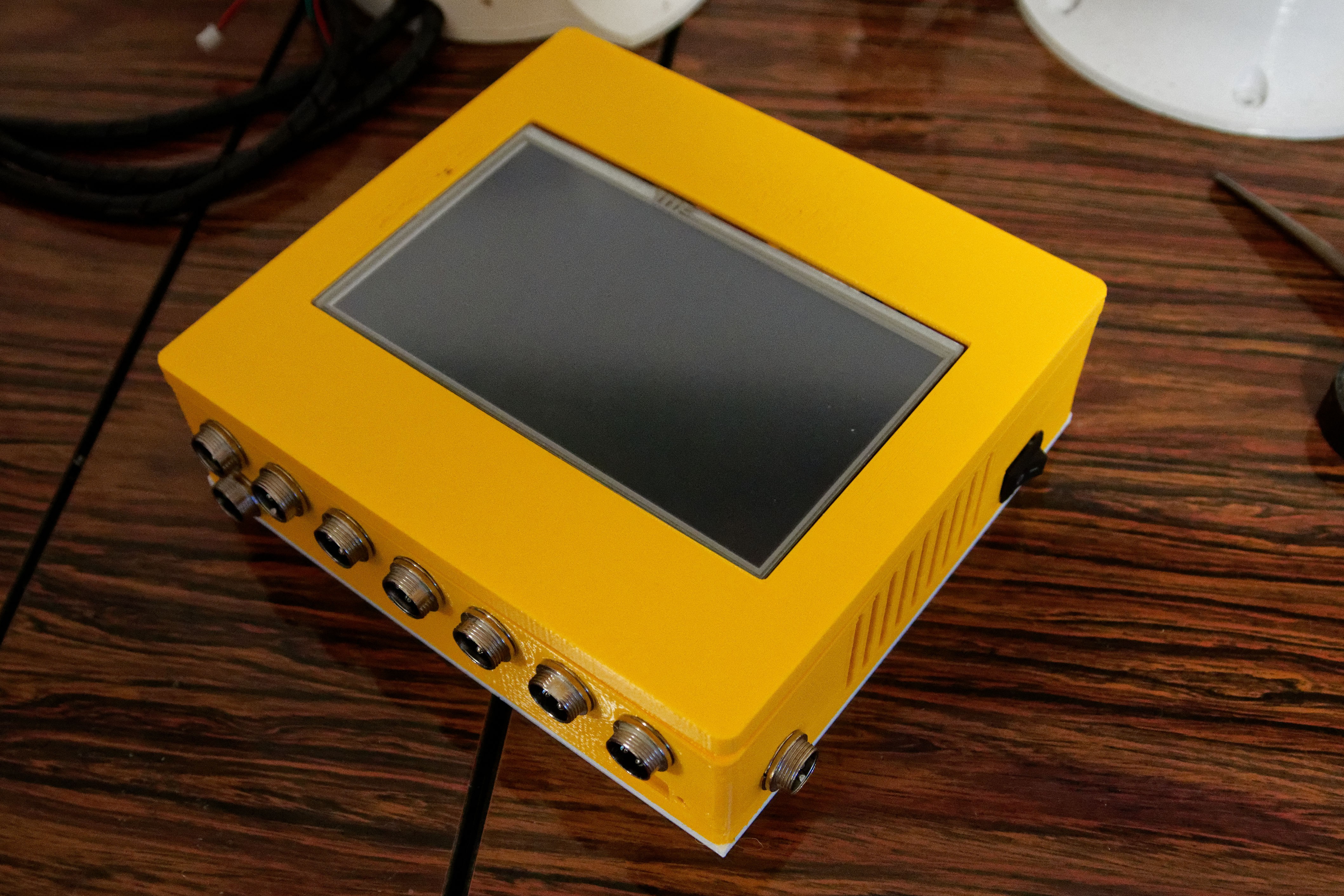 Side view to show the connectors and also the power switch on the box. That power switch cuts off the incoming 24V, so the motor drops out instantly.
 Having a switch at the 220V mains does not act fast enough to cut the motor power. I need instant shut off-during development of the software.
Discussions
Become a Hackaday.io Member
Create an account to leave a comment. Already have an account? Log In.