 timonsku
All parts arrived on Monday, the aluminium plate was great but 2 major pieces that went into printing came back horribly warped and oversized.
Granted they were both very large flat pieces, veery poor geometry for SLS printing. Still I while I was calculating with a bit of warping I did not calculate with THIS
Looks horrible doesn't it? The warping was one thing but the printing service also oversized the parts way too much so that they were 2mm longer than they should be, that's a terrible tolerance even at what size.
That a printing service oversize your parts before they go into print is actually normal, its done to compensate for the shrinking that occurs with this process. Normally this is very accurate and the final part will shrink to the dimension you anticipated, 0.2mm tolerance is reasonable to expect.
This didn't work obviously, the display frame piece had the same issues. So I had to resort to home production.
I first wanted to mill the two pieces but resorted to SLS printing and divided the parts into 4 sections due to size constraints of the printer, which then got glued together in the end. The final production will of course not rely on any form of printing but on some form of injection moulding or compression moulding (the back piece would be well suited for that). That all depends on the units made but even for low qty you can go with cheap aluminium moulds or urethane casting for really low qty.
If you are interested in the process, I posted updates in this Twitter thread (I usually make verbose updates over on Twitter): https://twitter.com/timonsku/status/1176259784871501825
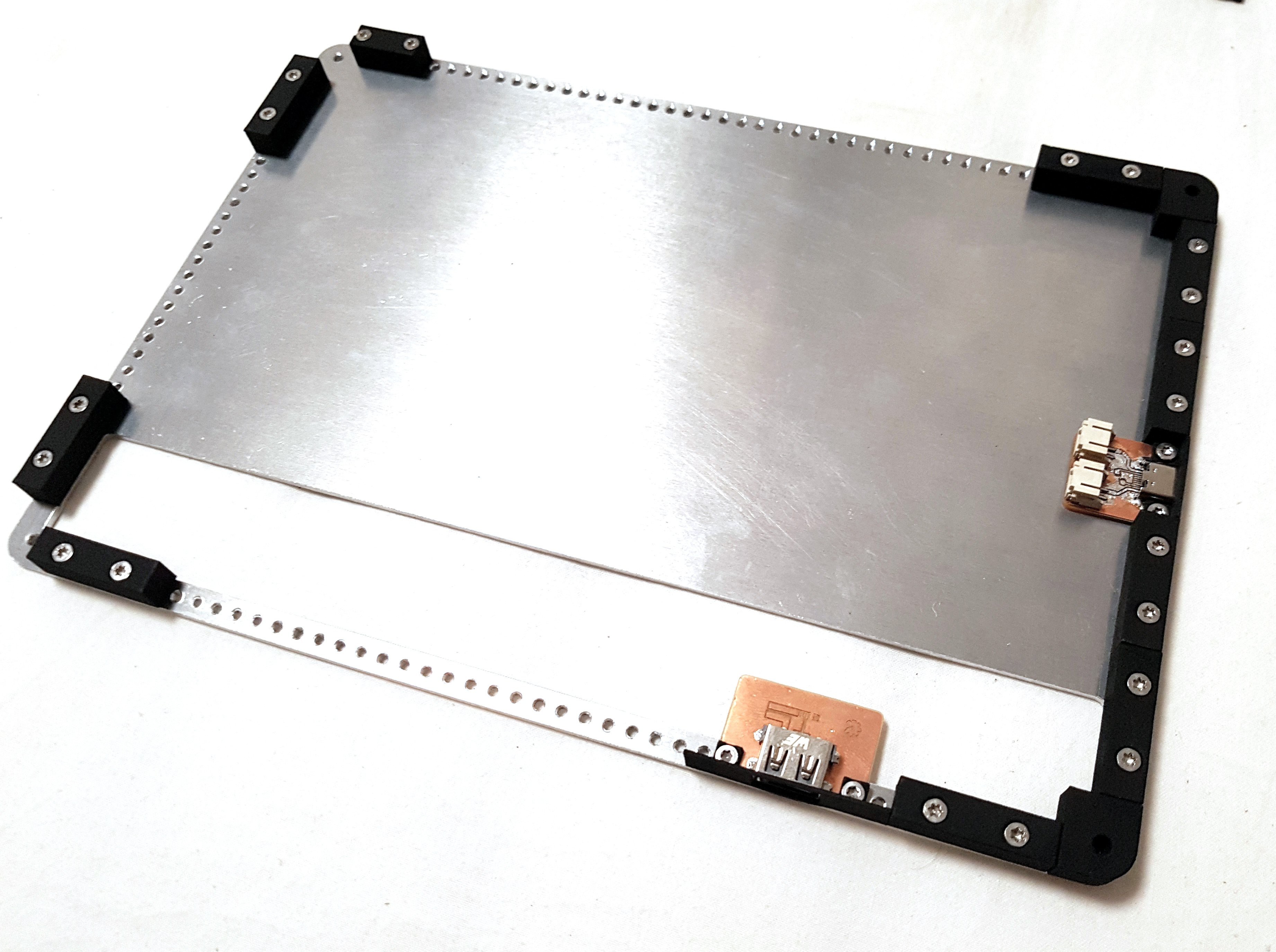
Before I show you the final pictures (well ok you probably saw them already when you visited the page, they replaced the old renderings). A few shots from the mounting plate and the "inside". I didn't mount any of the electronics except for 2 PCBs that I milled this week as well. I had to redo those because I polished some things with the mechanical layout which made the old V2 batch of PCBs not fully compatible, you can screw them down but they wont play nice with the spacers and are too close to the edge. The mainboard fits easily though when I reverse mount the module, as intended. You will see a full synergy in rev3 of the mainboard where the mounting plate will also be the heat sink.
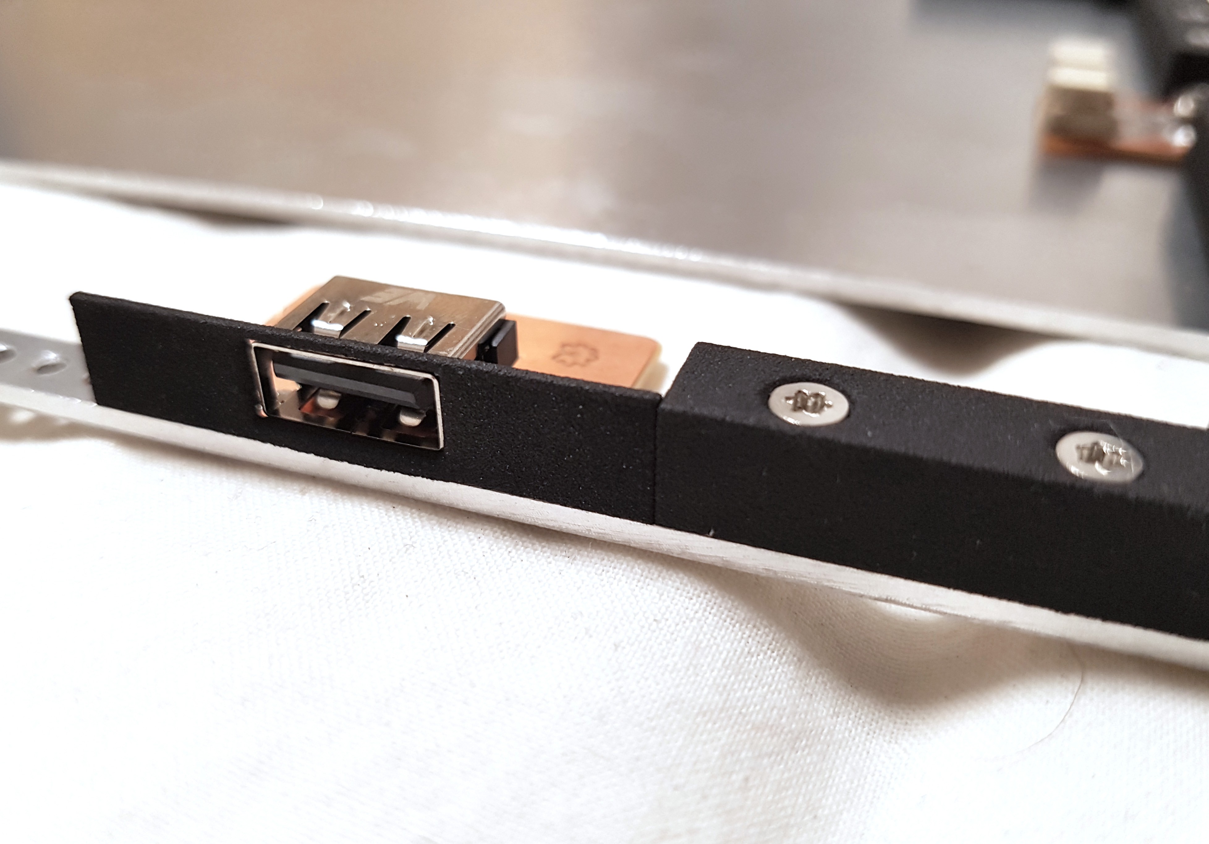
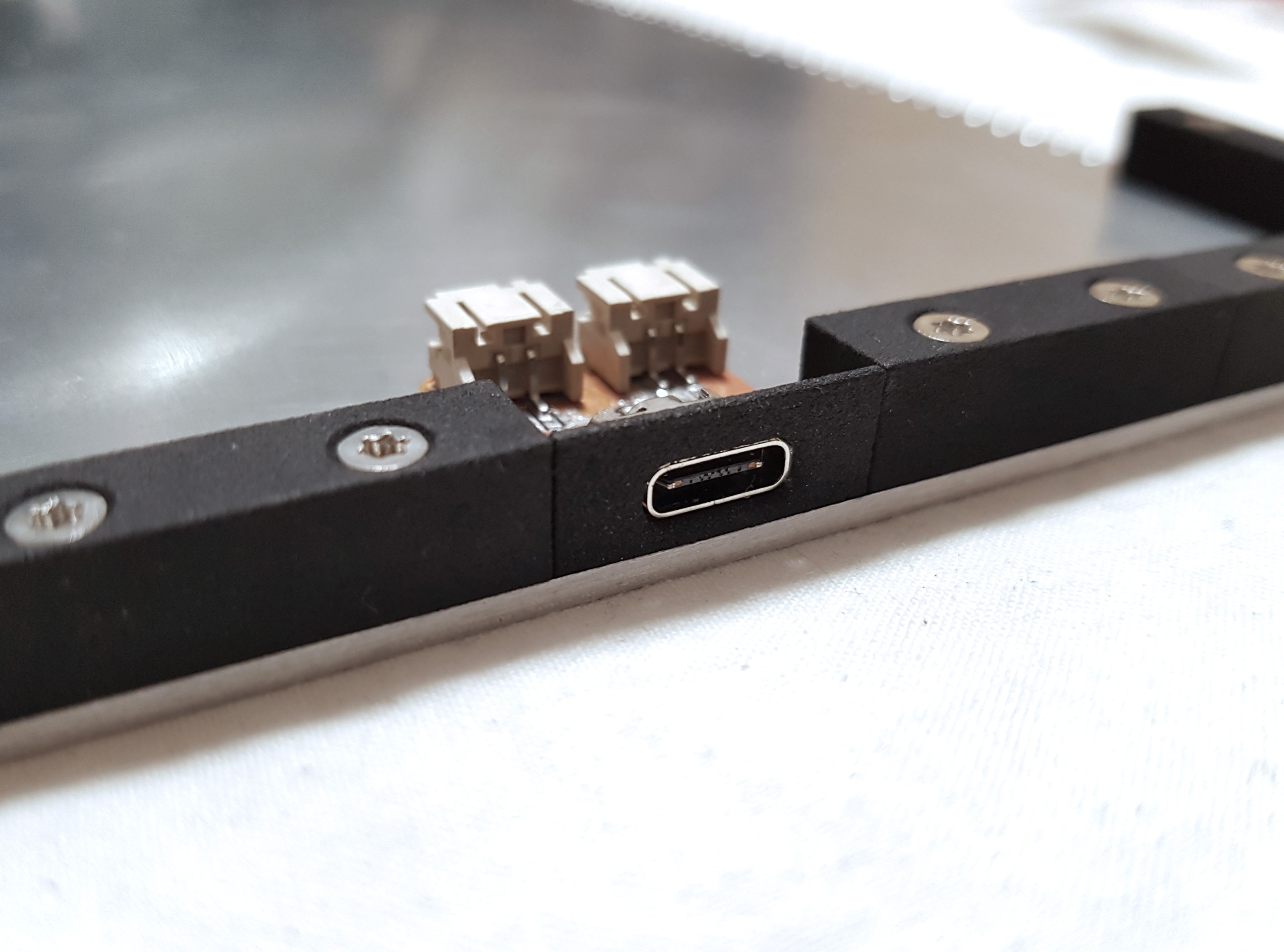
The two PCBs are both functional though, I left the USB-C with power only though, I didn't want to mill double sided to add traces for the USB2.0 connection. You might also notice there is not hole raster in the middle of the mounting plate. That's because I have not yet decided on a raster for that. I want that to be a lot larger (though still a multiple of 10mm), probably around 20mm. This will be determined with v3 of the motherboard. I will then add those manually, for now I only need a mounting point for the motherboard, that's easy to drill and tap manually. If I had chosen one by random it could have made things worse if I found out I need a different raster in the end. That way I'm flexible.
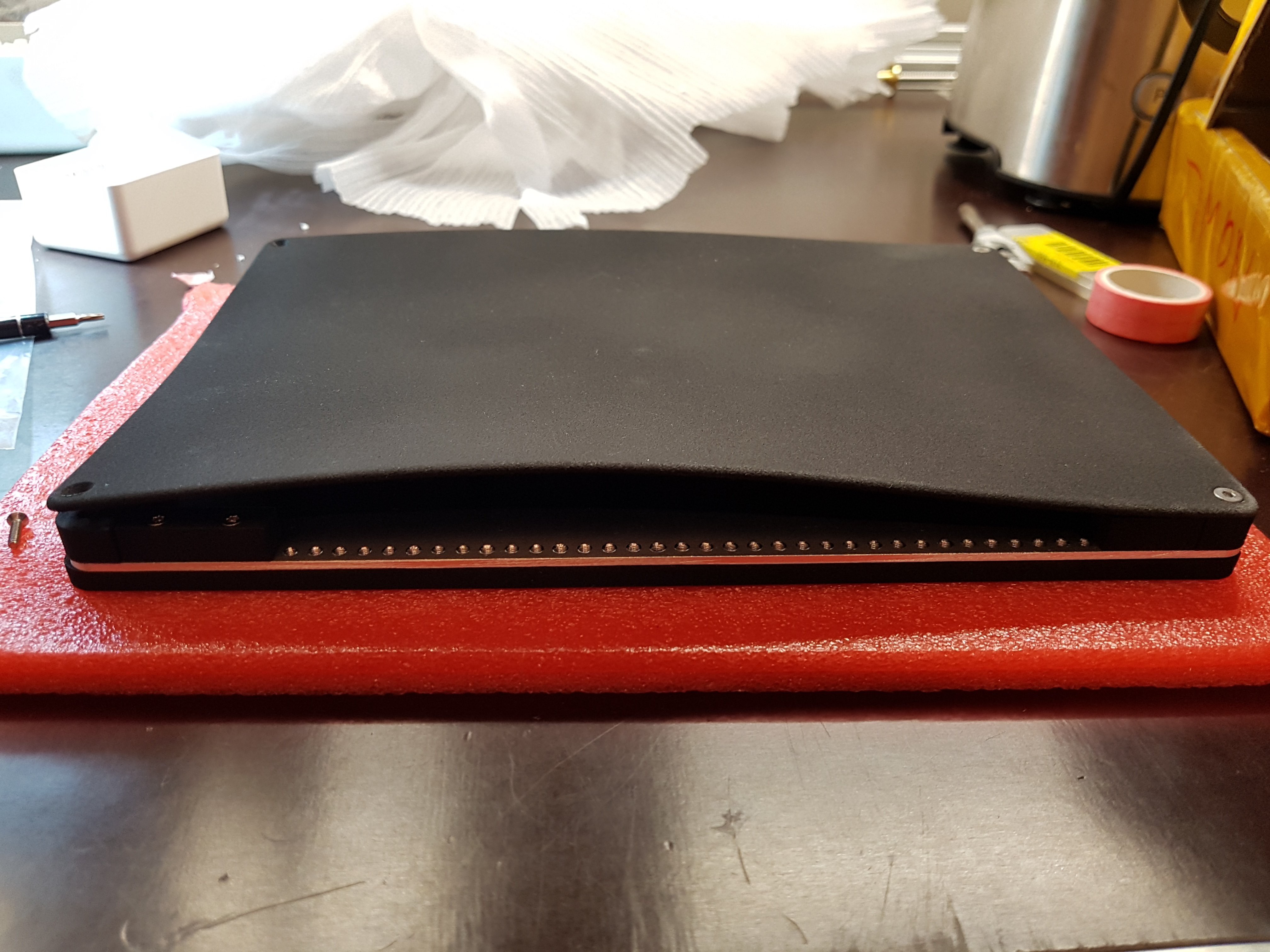
And now finally the assembled prototype. I made sure to make a lot of pretty pictures :)


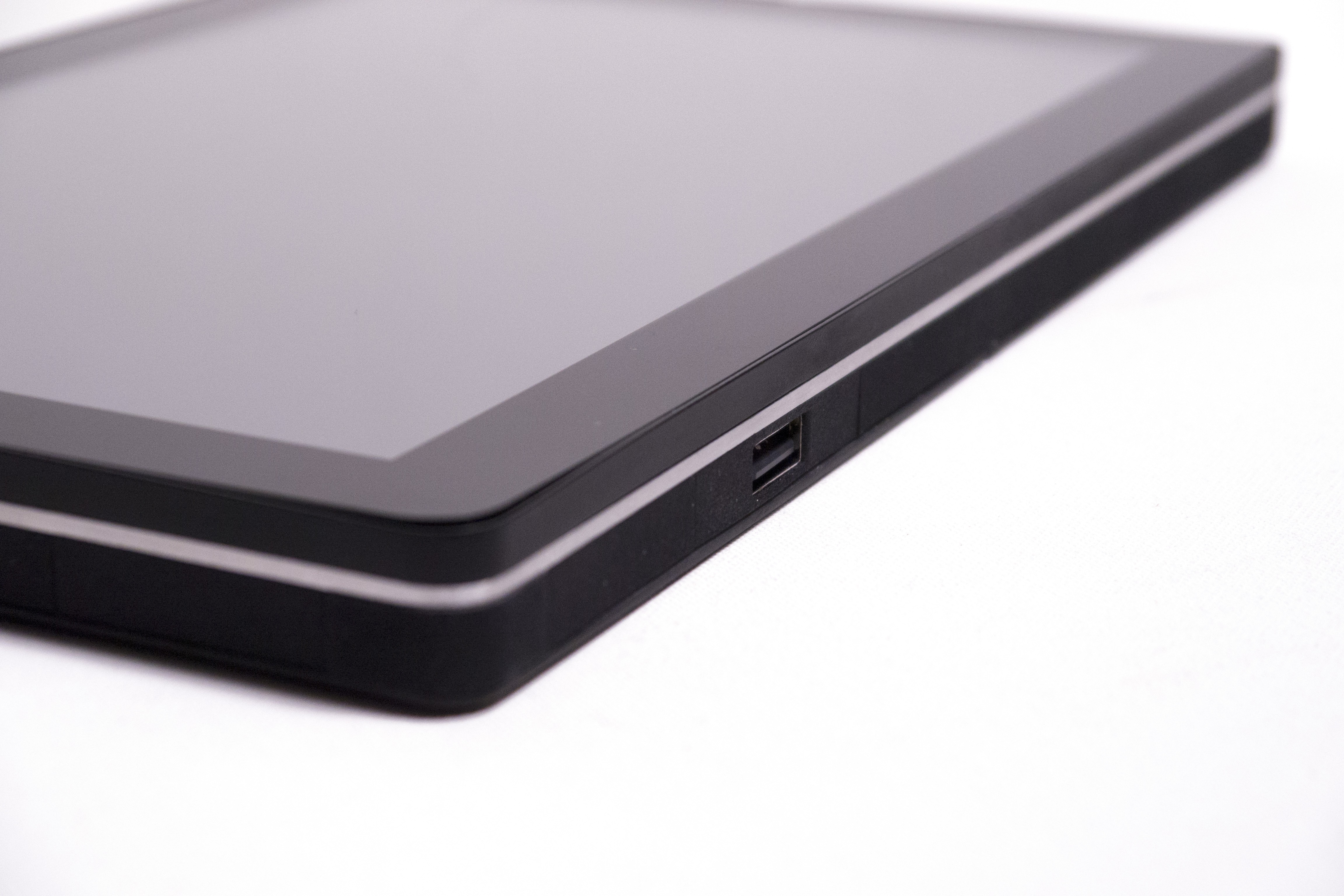
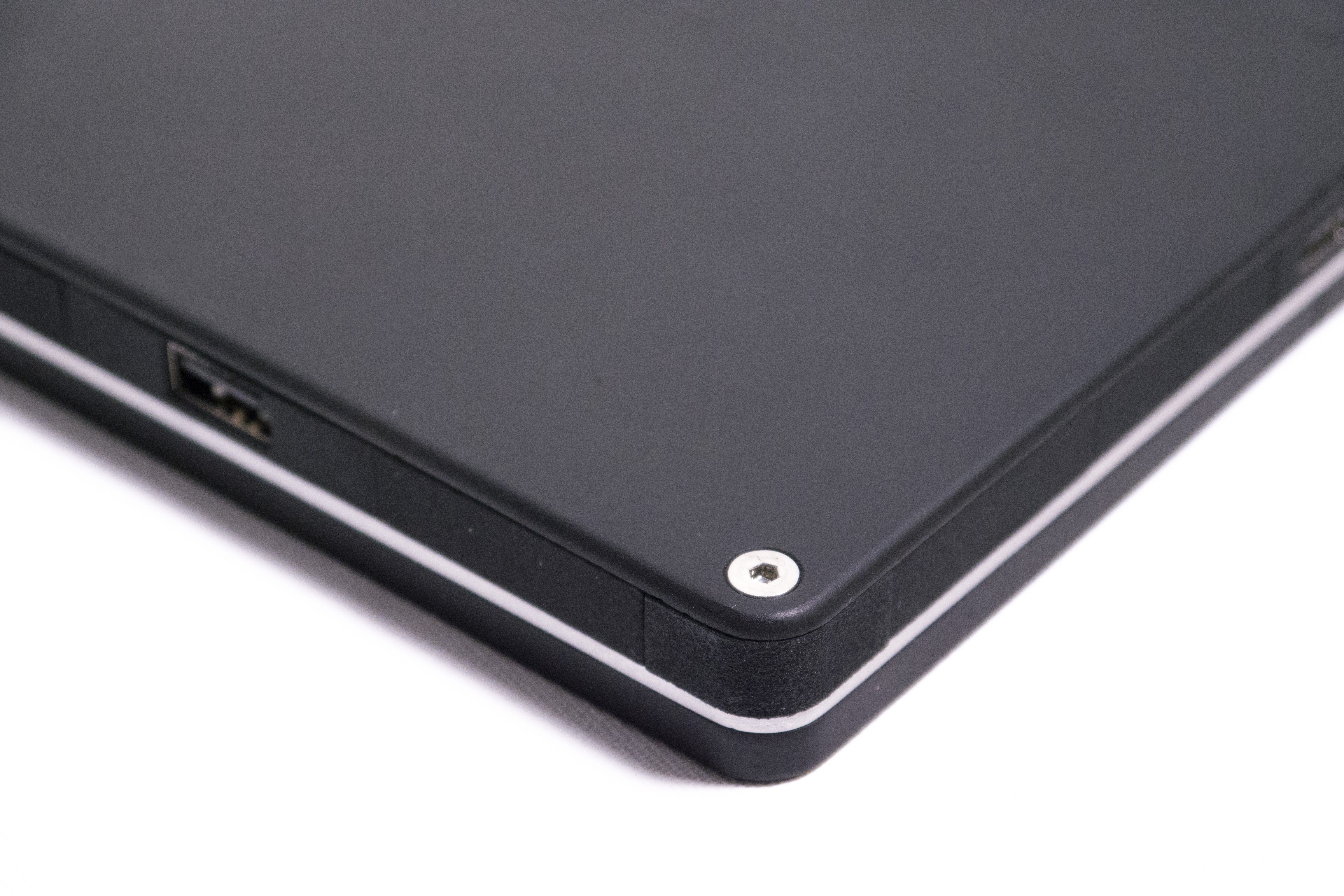
No more warping yay \o/
Discussions
Become a Hackaday.io Member
Create an account to leave a comment. Already have an account? Log In.
This looks great! Were you able to work out the video issues? Also is this the module mounted so that the aluminum plate is the heat sink?
Are you sure? yes | no
That is coming with the next rev.3 motherboard revision
Are you sure? yes | no
That is without the battery, right? Or is the battery going to be fit in there somewhere as well?
Are you sure? yes | no
I always planned with a battery of course, the motherboard takes up about a quarter to a third of the internal space so there is plenty of space left for internal hardware e.g. battery. Thickness wise you could also have two cells stacked with the 8mm high blocks. With the thin form factor probably only one.
So far I was planning with 20Wh battery capacity. Pouch cells with built-in protection.
Are you sure? yes | no
Asking just in case, because it recently happened to my phone and I was pleasantly surprised how the mechanical construction took it: what happens when the battery gets puffy and expands?
Are you sure? yes | no
@de∫hipu The mounting plate would protect the screen so the back would just also start to bulge. So at least it wouldn't explode in your face if that were to happen :)
The back is in-expensive if you would experience a more catastrophic failure of the battery, that would be easy to replace.
Are you sure? yes | no
I'm also a fan of LiFePo4 a much safer chemistry than standard LiPo
Are you sure? yes | no