 SHAOS
SHAOSNow it looks much closer to completion:
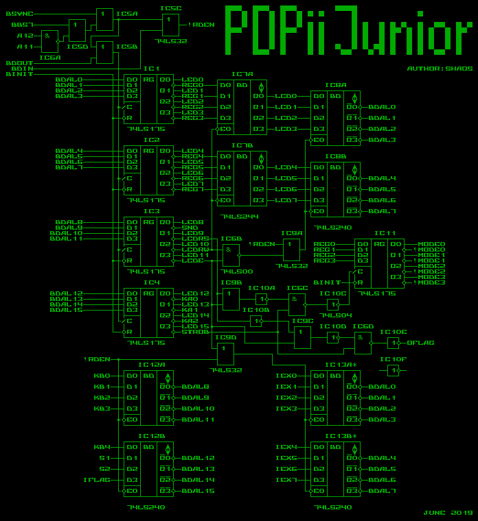
IC11 is bank register, that store 4 bits when LCDE=0, LCDRS=0 and STROB=1 for a short period of time and it's cleaned on boot (when BINIT=0). If LCDE=0 and LCDRS=1 then STROB goes out as OFLAG (will be used in future). Higher byte of the word is always going back to the BBQ-bus when !RDEN is 0 (Q-bus read cycle from address 0xF800...0xFFFE), but lower byte can be LCD data output if !RDEN=0, LCDE=1 and LCDRW=1 (read from LCD) or IEX0...IEX7 if !RDEN=0 and LCDE=0 (LCD disabled). Those 8 extra inputs are reserved for future so if it's not used then IC13 could be omited. REG0...REG7 are connected to LCD data bus only when LCDRW=0 (write to LCD).
Next I should add ROM 27C1024 and show how to mix RAM module and ROM address signals with some logic to get memory modes described earlier - TO BE CONTINUED
Discussions
Become a Hackaday.io Member
Create an account to leave a comment. Already have an account? Log In.
Out of curiosity, what EDA is this?
Are you sure? yes | no
My own EDA :)
http://Circuits.CC
Are you sure? yes | no
Nice! :)
Are you sure? yes | no