 Lubos Horacek
First thing after receiving the table and tested it actually works, I opened the controller unit and tried to look it it's the same as some other tables already described around here or elsewhere on the internet.
Unfortunately the wiring was different from table to table, so I tried googling anything I could find on the controller and main unit. No luck again, so I took super cheap oscilloscope ( DSO138mini as I was still waiting for my logic analyser .. ) and tried different pins of the controller.
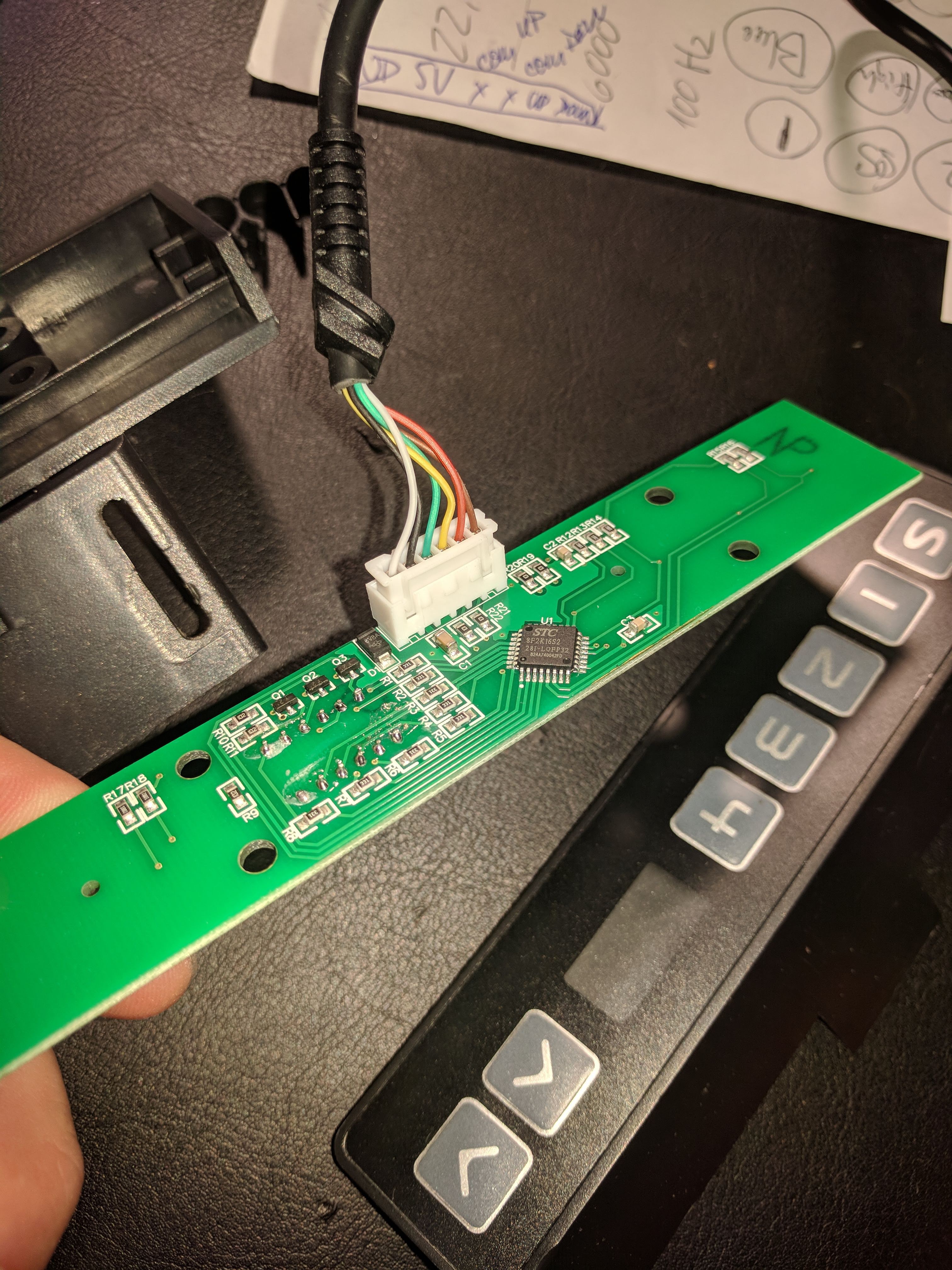
By pressing controller buttons, I figured it goes:
- GND
- Vcc
- Rx
- Tx
- Button Down
- Button Up
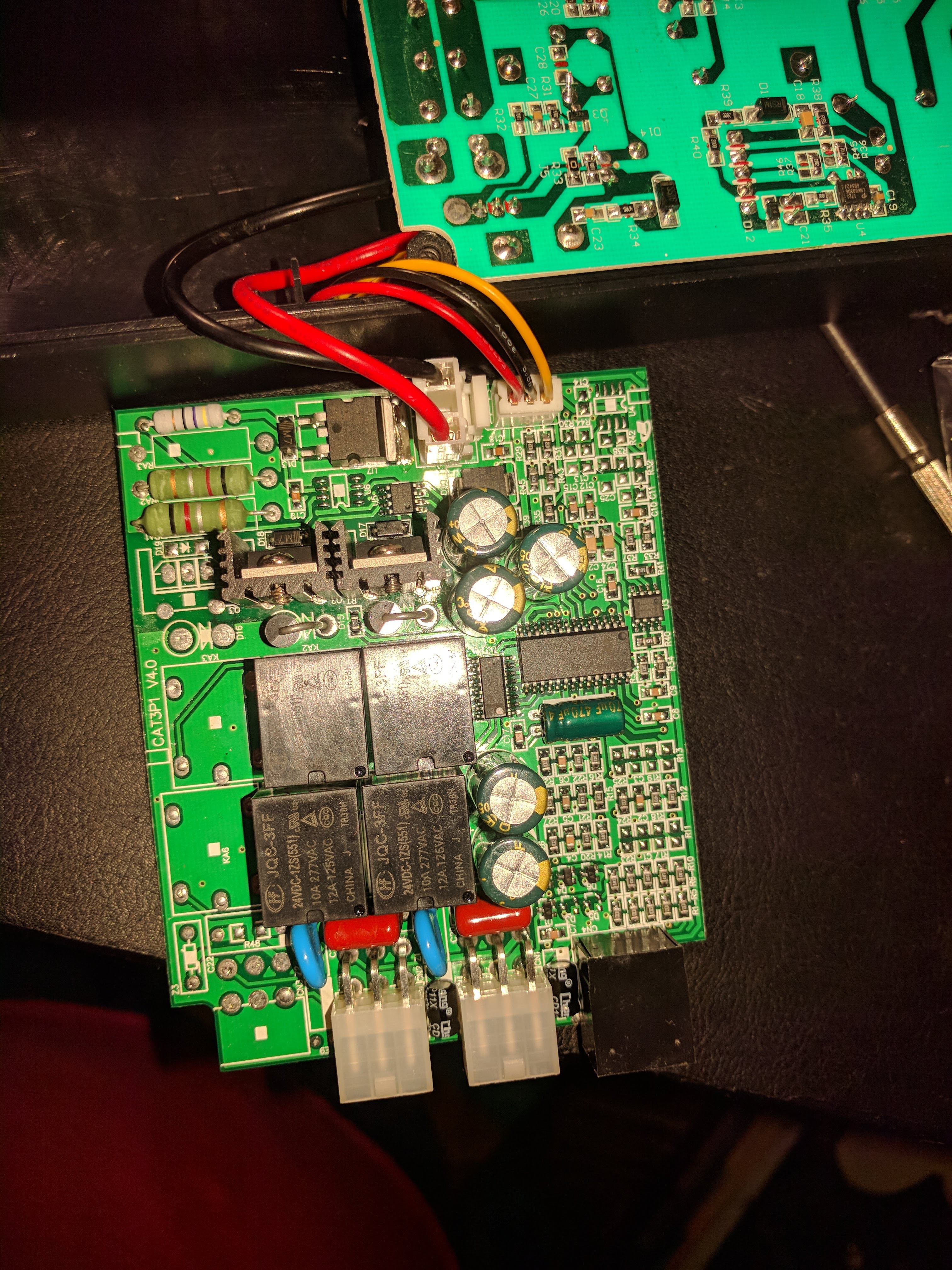
All pins being high when idle, Rx was having quite a lot of messages being sent by the main unit to the controller. Rx contained only messages when I pushed some button. I tried letting the table reach remote position and disconnecting the controller mid-way to see if it had some role in controlling the end position. Turned out not to be true and as soon as the button was pressed on the controller, main unit took care of travelling to given position and stopping.
So next thing was figuring out what are the messages being sent. By checking the scope and the length of pulses, I figured it was 9600bps rate as on most of those controllers. So I've hooked ESP8266 Software serial to these repeating the stuff to Serial console. I tried to display binary output, but it was all over the place. Took me while to test outputting HEX and then compensating padding by 0 for values less than 16. Suddenly all messages were same length with only two bytes changing during the movement with 16bit position in little endian format stored in 3rd and 4th byte of the message:
AA A6 [low byte] [high byte] 0C00
Then I checked the controller's Tx and this is what it sent:
Wake up: 55 AA F0 F0 F0
Sleep: 55 FC
Mem1: 55AAD1D1D1
Mem2: 55AAD2D2D2
Mem3: 55AAD3D3D3
Mem4: 55AAD7D7D7
Stop: 55AAE3E3E3
With some more messages for storing new values to memory, but I was most interested WakeUp, Memory recall and Stop. Turned out WakeUp does not have to be called before triggering memory and sleep is handled by the main unit as well. And as memories we not specific heights, but fixed messages, it turned out to be pretty simple.
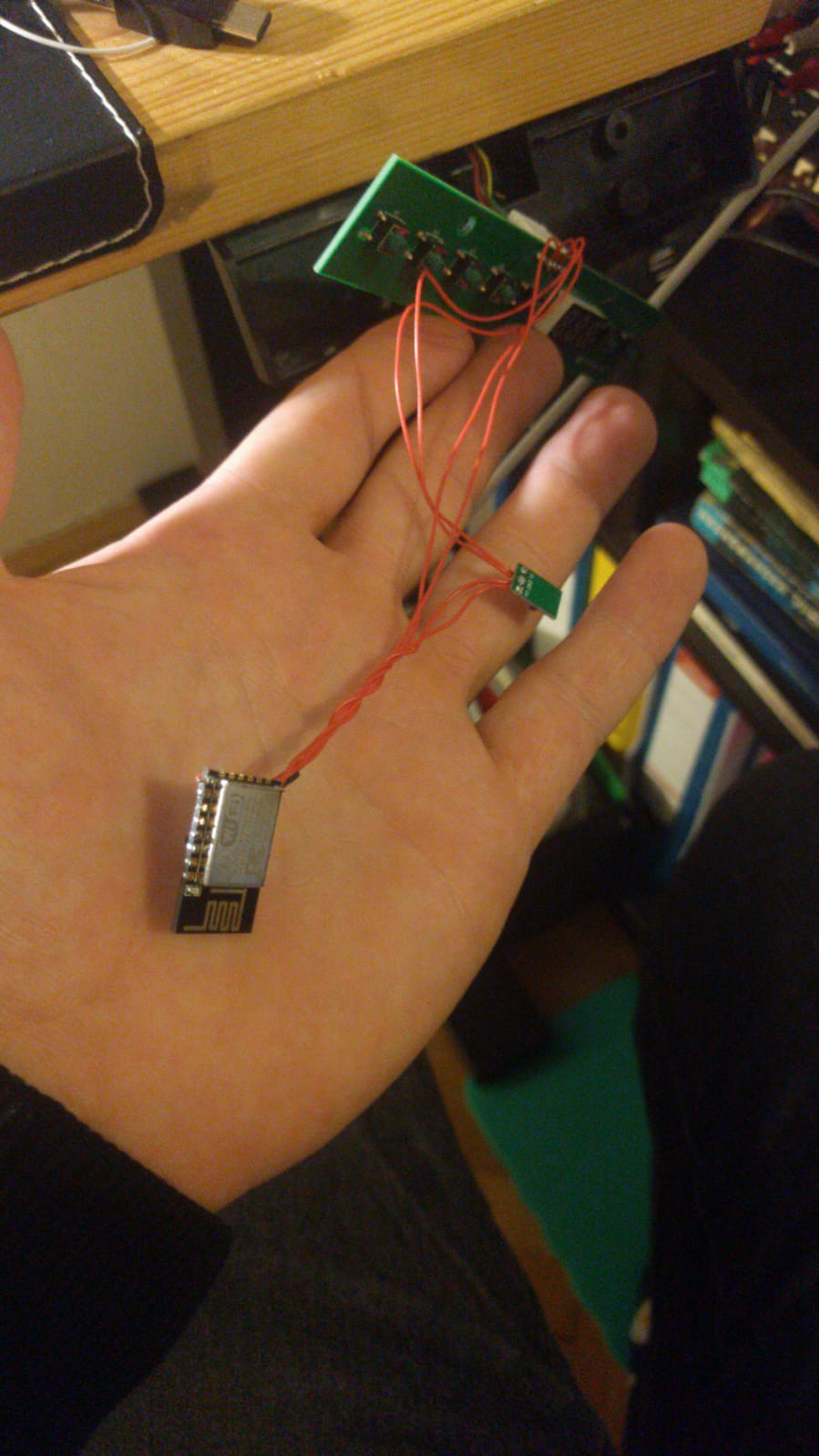
After testing the comms with I added one diode to the Tx of of ESP8266, so it worked alongside the normal controller and not keeping it HIGH all the time.
First I bothered with level-adjusting the signals, but turned out that ESP8266 pins can handle up to 5V levels, so I've ditched all the unnecessary stuff and then moved to ESP-12E module and small step-down to fit in to original controller enclosure.
#include <SoftwareSerial.h>
SoftwareSerial mySoftwareSerial(5, 16, false);
byte last[3];

void setup() {
  Serial.begin(9600);
  mySoftwareSerial.begin(9600);
  Serial.println("\nSoftware serial test started");
}

void loop() {
  if(Serial.available()){
    byte in = Serial.read();
    if(in == '1'){
      Serial.println("\nMemory 1");

      mySoftwareSerial.write(0x55);
      mySoftwareSerial.write(0xAA);
      mySoftwareSerial.write(0xD1);
      mySoftwareSerial.write(0xD1);
      mySoftwareSerial.write(0xD1);
    }
    // add more mem recalls to test
  }

  if(mySoftwareSerial.available()){
    while(mySoftwareSerial.available()){
      byte in = mySoftwareSerial.read();

      if(in == 0x55){
        Serial.println();
      }
       if(in < 16){
        Serial.print('0');
      }
      Serial.print(in, HEX);

      if(last[2] == 0xAA && last[1] == 0xA6){
        Serial.print(" Heigh ");
        Serial.print((255*in) + last[0], DEC);
      }

      last[2] = last[1];
      last[1] = last[0];
      last[0] = in;
      yield();
    }
  }
}
Discussions
Become a Hackaday.io Member
Create an account to leave a comment. Already have an account? Log In.