 Marcos
Our last episode covering the FPGA capabilities deserved a quick followup to shed some light into what's coming next in the hopefully near future:
Icestudio GUI getting huge improvements
Hardcore developers will handle any problem with any fpga using any language to get things done. For the rest of us, its neat when the user interface is friendlier than a bunch of HDL files.
Several updates happened to the icestudio.io project, with massive speedups showing up in the nighties. This speedup is allowing to work with really large FPGA projects.
Lets see a couple of examples from the developers mailing list. The list is in Spanish so its good to unearth that huge effort and show a bit what's going on there.
Z80 processor + peripherals
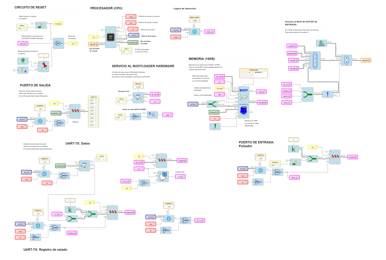
This is not just a drawing, this is the actual view in the ice40 Icestudio editor. You can actually drop a Z80 CPU, UART, RAM, Bootloader and GPIO blocks into icestudio. Verify, synthesise, and upload to the target is a breeze.
Yes, this is really happening, in a fully open source FPGA toolchain! It was about time, after all we were promised 2019 was the year of the FPGAs!
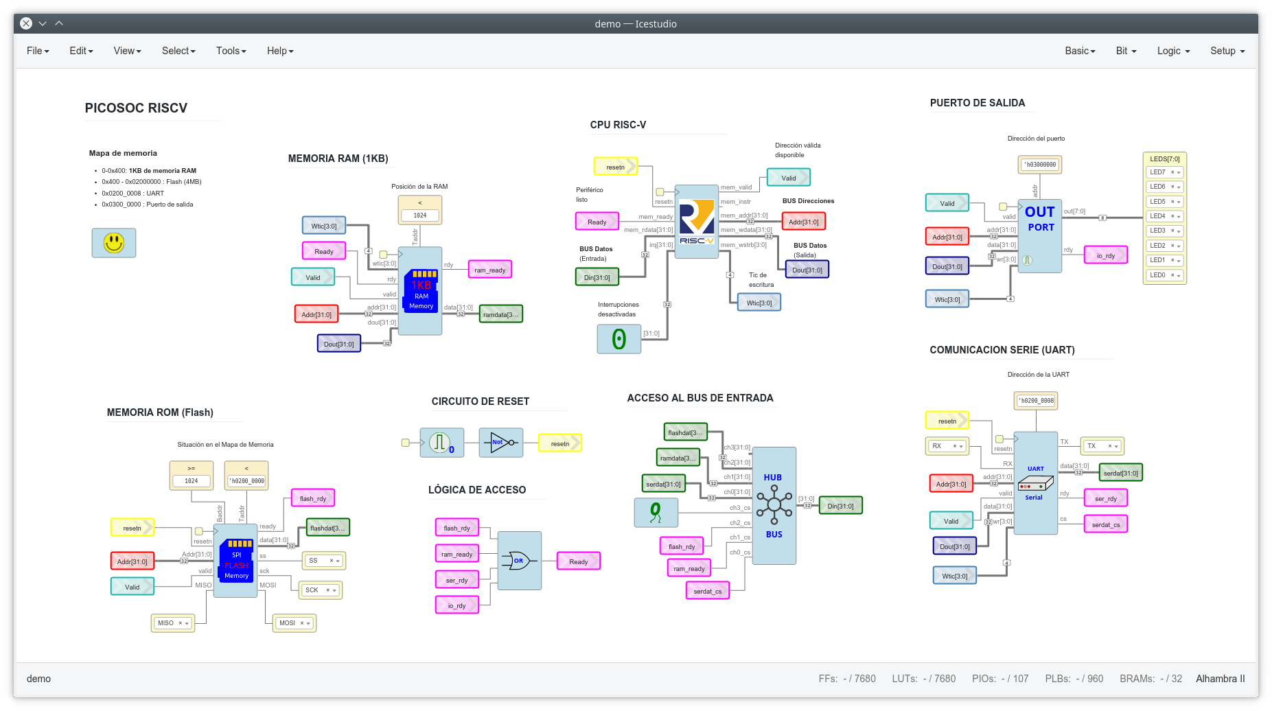
RISC-V + peripherals
Z80 not cool enough for you?
There is a RISC-V core available and passing tests on the ice40 devices, together with a UART, RAM and external flash management ready for you to discover and try out. Kudos to Obijuan for sharing this demo!
The coolest bit of this is that you can use gcc to compile C code that runs in this softcore, and the code example is awesome, directly accessing your custom "peripheral" from the address map:
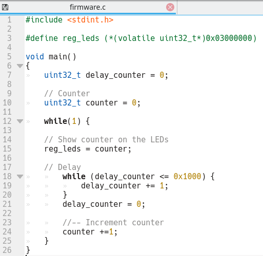
You can see it doesn't need any fancy include, and when you consider it was you who built the whole cpu logic, its just mindblowing.
An actual motor control application
Alright alright, that toolchain is very cool, but how does it benefit my motor control application?
The main point of Axiom having an FPGA is to digitize earlier the analog signals.
These digitizers are footprint compatible with the AMC1302 iso-amps currently installed which are actually delta sigma converters but they convert the signal back to analog domain. By swapping them you can digitize right at the High Voltage domain, and it stays digital until it reaches the microcontroller for field oriented control calculations.
What's the benefit?
First you can ditch all these analog signal processing components, they are a big chunk of the BOM and pcb area!
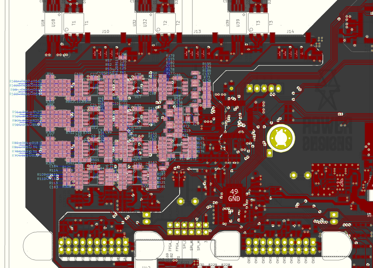
All these components can be removed if Axiom goes digital
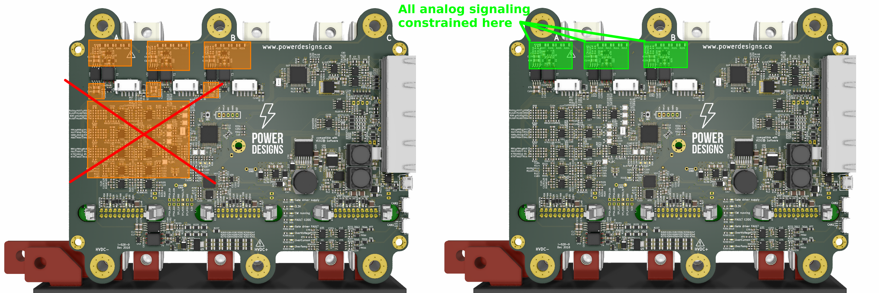
Not only they add cost to the BOM, but most importantly they add ageing, temperature and tolerance drifts; supply rail variations and EMI will creep up into the measurements, and in these critical applications, every parameter drift has to be studied to perform the design assurance our big customers are already requesting.
For example if the signal chain has x2 opamps, x7 1% resistors and x4 10% capacitors, you can calculate the worst case scenario in which the signal chain will have 10% of error. That's likely unacceptable, so you run a Monte Carlo analysis that tells you that 99.8% of the boards will meet <5% tolerance, but now you need to test every board under various conditions looking for the 0.2% that needs to be scrapped or somehow tuned.
Enter the digital signal path
Everything we did in the analog domain we can do it in its digital counterpart. Drop a delta sigma demodulator block, a sinc filter, a decimation filter and you are ready to go. This takes only a few hundred logic blocks.
 This signal chain and its benefits are well documented in this article by Analog Devices
For the hardware overcurrent/overvoltage comparators there are methods that will detect the incoming fault within 4 us with a few logic gates. That's usually done by branching off another filter from the 1-bit stream but with quicker response time. So for example if you get seven "1" in a row that can be enough to indicate a fault condition and shut down the drive, and for safety standards this count as "hardware-based protection".
Repeat the signal chain 7 times (x3 currents and x4 voltages), send the data over high speed SPI and you're done. Most current sensors have analog outputs, but we already developed a current sensor with delta sigma output that is actually lower cost than its HALL counterparts.
You can sync the sampling exactly on the center of the PMW activity like the MCU does, and by tweaking a bit the OSR you can place notch exactly at your pwm freq, removing a lot of noise from your signal.
 Analog's article goes in depth explaining how the impulse response attenuates the weight of the samples taken at the switching times.
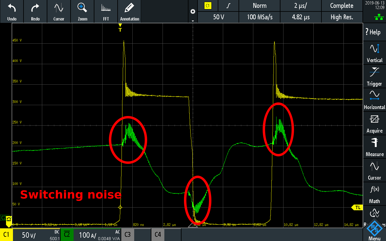
Noise near switching events weigh less after going through the impulse response of the sinc3 filter
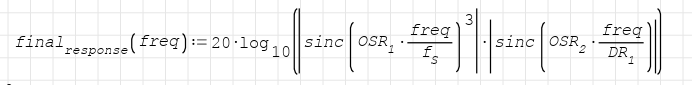
We have run our own math to produce the correct combination of modulation frequency, oversampling and decimation to locate the notches in the digital filter chain at exactly 18kHz which is our target switching frequency. Need a different frequency? Tune a few parameters and you're ready to go.
The response plot you get is nothing short of amazing:
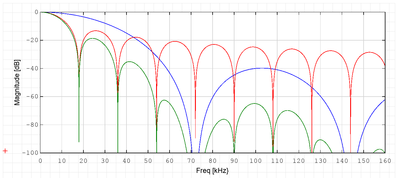
Not only you get a notch in your 18kHz, but all the harmonics in the green plot get notched-out
Basic tests and results were promising - no one got hurt! -
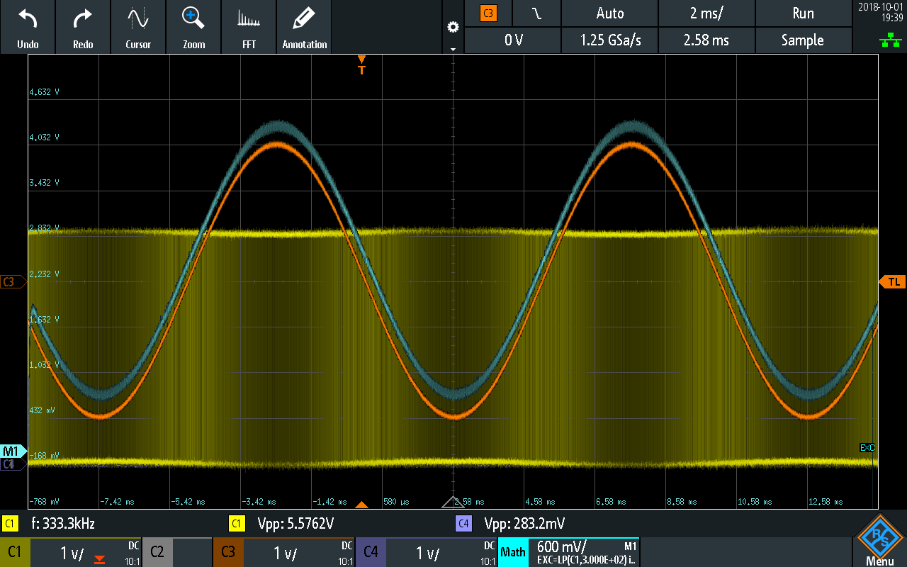
Yellow channel: Delta Sigma output of a 100Hz sine
Sinc3 filter and decimation was developed in verilog, ready to be replicated in the system:
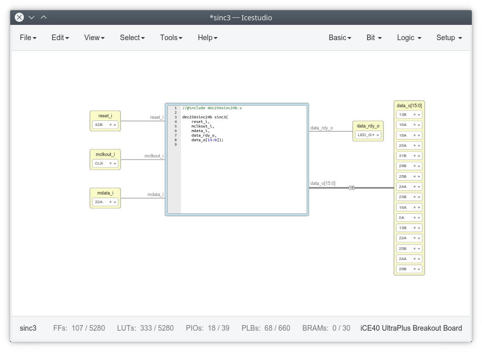
Icestudio makes testbenching easier, and results are shown in gtkwave
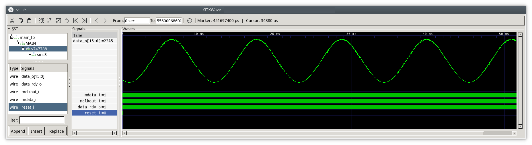
Testbench of Axiom delta sigma demodulator+sinc3 using real data from a sensor
If we really go down this path we can drop in the 144 pin STM32F4 that can expose the full bus on the pins and gain instant access to the data as a directly memory-mapped area instead of SPI.
So this is a peek into the future of Axiom, the groundwork is ready but its a steep development effort that requires quite a bit of funding, and right now we are really busy with documentation for the future users as the current embodiment is already earth-shattering!
Until then, have fun!
Discussions
Become a Hackaday.io Member
Create an account to leave a comment. Already have an account? Log In.
I am just curious, doesn't the DFSDM block of the STM32H7 and STM32L5 implement the digital functions that you needed? Including an analog watchdog that can detect "short-circuits" of consecutive 1s and 0s? Or is there something I am missing?
Really cool project by the way.
Are you sure? yes | no
Yup, I'm aware of those peripherals in H7 family, but there are 2 roadblocks to use that:
* VESC is a 100k source lines of code effort that is not easy to migrate to a different MCU. There is one developer working on this atm, but its far from being mergeable.
* High end MCUs usually have 3 or 4 blocks like ST's DFSDM. That's enough for 3 phase currents and DC Link voltage, but Axiom also measures 3 phase voltages for BEMF tracking, so it would make use of 7 demodulators.
Are you sure? yes | no
May I ask, what are the reasons why you chose to fork VESC firmware instead of say spinning your own FOC algorithm? You guys are very skilled engineers and I'd imagine developing a custom FOC algorithm wouldn't be too difficult.
I've looked into VESC source code and, at least for me, have found quite a few issues with it.
Also curious, would sampling the phase voltages with a 16bit SAR ADC (like the one on the STM32H7) be unsatisfactory? Adding a filter capacitor can be used to filter out switching noise and the phase delay compensated for very precisely using some trigonometry math tricks.
Are you sure? yes | no
Yeah, we do have planned an automotive qualifiable controller, we started with vesc to work on the hardware side with proven firmware and a large user base, so we can later work on our own IP
Are you sure? yes | no
I am really excited every time I check in on this project and there is an update! I wish you were getting more attention and feedback, I think you deserve it! While I cannot comment on your work as a subject matter expert, what I see is top notch engineering work being shared with a clarity and openness we can all aspire to.
What draws me to this work personally is that inverters are at the core of all these subfields that interest me: electric vehicles, DC->AC inverters, switch mode power supplies, audio amplifiers, variable frequency drives, and yet each subfield gets its own application-specific implementation as if these are only tangentially related related technologies. At least that is my impression as a non electrical engineer. Please correct me if I am totally wrong about this.
Clearly it's important for your team to focus on the task at hand, but I hope this work serves as the basis for creating open and universal power inverter development tool kit in the future.
Are you sure? yes | no
Thanks for following this development, and especially for letting us know! Motivation is really important when you have so many tasks ahead.
The power electronics field is full of small details, some not well documented, some are expensive to learn or test (transformer design for example). Its part of the beauty of it I think, we will slowly unravel and dominate its mysteries... and when we do... GaN!
Are you sure? yes | no