 Marcos
Another performance contribution to VESC from powerdesigns!
Now that we earned some deep insights about the inner workings of IPM machines, lets recap what is MTPA about.
MTPA stands for Maximum Torque Per Amp, which means that for a given current flowing into the motor phases it produces the maximum torque possible. We'll find out the benefits doesn't stop there.
Typical FOC implementations will drive flux-producing current (id) to zero and map the user throttle directly to the "torque generating current", (iq). This works great for cheap, non-salient SMPM motors that have a constant inductance throughout a complete revolution, but its not the complete picture.
Motors commonly found in automotive applications (Nissan Leaf, Tesla M3, BMW's, etc) are IPM motors with large reluctance that need a special algorithm to maximize the potential of the machine. Lower power IPM motors are also seen in high reliability and high dynamic range applications because the magnets aren't just glued to a surface and because they have a nice and extended constant power range.
So, will this improve my ebike or skateboard? Well, probably not much, cheap motors have usually very low saliency.
The torque equation
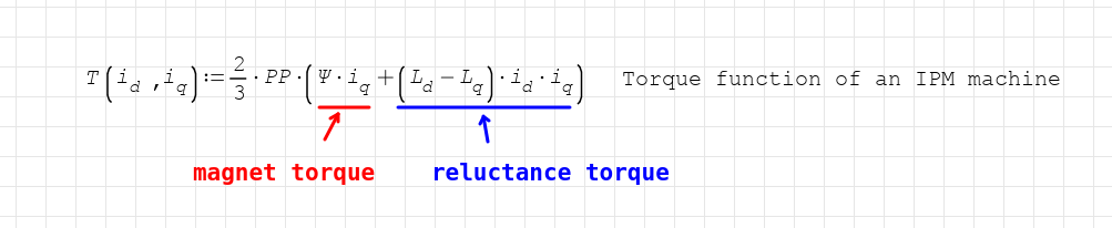
- iq=0 will always produce zero torque
- id doesn't produce any torque if (Ld-Lq) is zero (an outrunner motor for example)
- There is an optimum id,iq setpoint that maximizes the torque
The end result is something like this that shows each torque component.
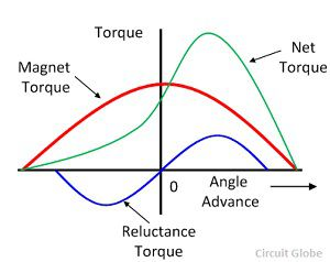
Because id,iq are 90° apart from each other, if id=0, the resulting vector angle is 0°, meaning no reluctance torque is produced. When we start adding id the reluctance torque increases, and the total produced torque becomes the sum of both traces.
The most valuable part
By far the best thing we got out of this is understanding better the motor control theory. We developed math and reproduced equations and tools to produce a d-q axis plot of any IPM machine.
This is for example a customer's IPM motor for a custom-made extreme density motor controller we made for them.
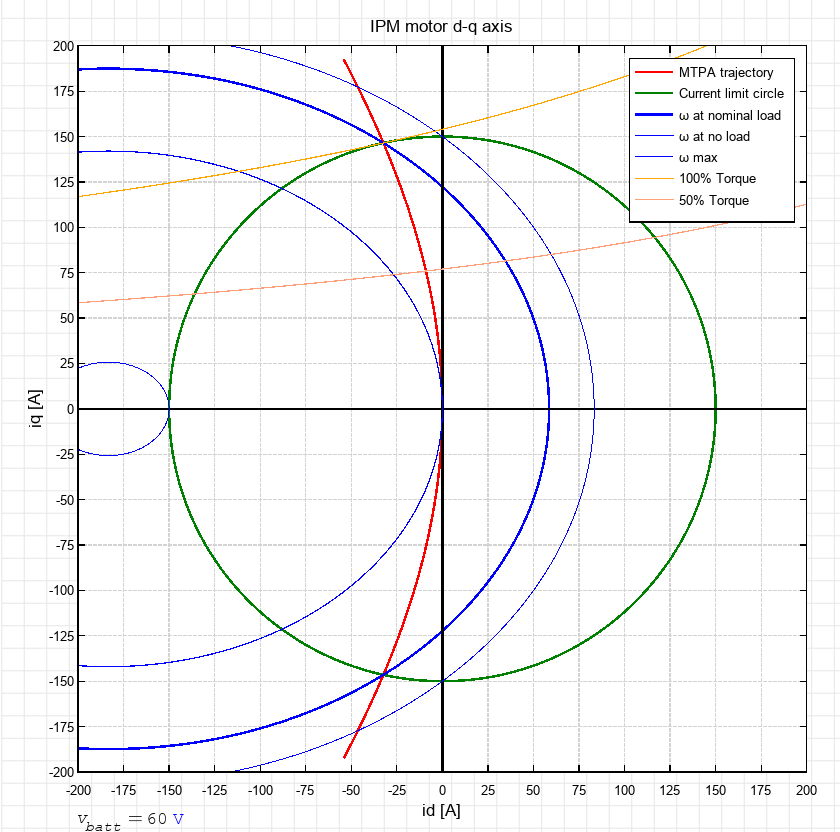
On a quick glance you can see at once:
- the ideal MTPA trajectory (red)
- how salient the machine is (how tilted the red trajectory is)
- the current limit you are operating on (green)
- the voltage/speed limit ellipses (blue)
- the torque profile of the machine (orange)
- and once you understand it you can easily see the exact id,iq currents needed to operate at any allowed speed/current target.
We also found the limitations of conventional Field Weakening algorithms and why they need to be improved if we want a linear throttle response on an IPM motor.
Side benefits!
MTPA is not only about increasing torque. The addition of id current also increases the full load base speed of the machine in the same way Field Weakening does. So you have more torque, more speed, and hence, more power!
In the Nissan Leaf motor, the improvement is huge. You can see the peak power operating point shifting from the right circle to the left towards a smaller (higher speed) ellipse while intersecting a higher torque torque curve.
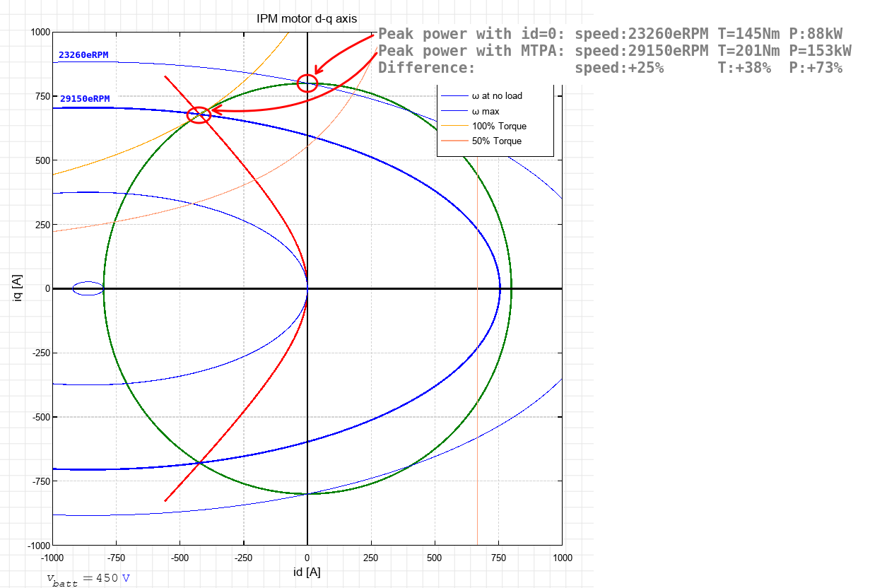
That's right, this algorithm provides:
- 25% extra speed
- 38% extra torque
- 73% extra power
Implementing the optimization
You can search in the literature the details of the math to find the optimum id, iq (involves derivatives). In order to find the peak torque it boils down to this equation:
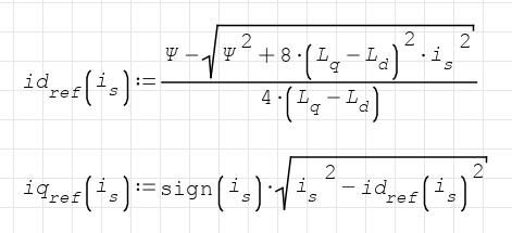
So the firmware will take the current reference is and separate it into the optimized id,iq components.
We added to the GUI the single parameter that controls the MTPA algorithm:
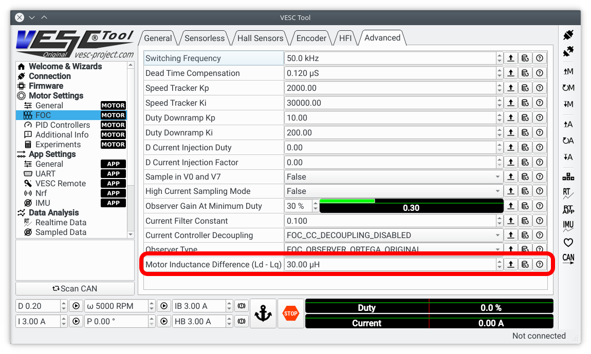
The Ld-Lq parameter can be measured from the vesc command line or by manually searching the peak torque on a dyno.
Besides that there were a couple of errors in both VESC firmware and in Texas Instruments app notes that had to be fixed in order for MTPA to work.
You can see the code details in the pull request to merge the new feature
https://github.com/vedderb/bldc/pull/179
Testing!
The pull request comes after long testing sessions. Let's see the algorithm in action:
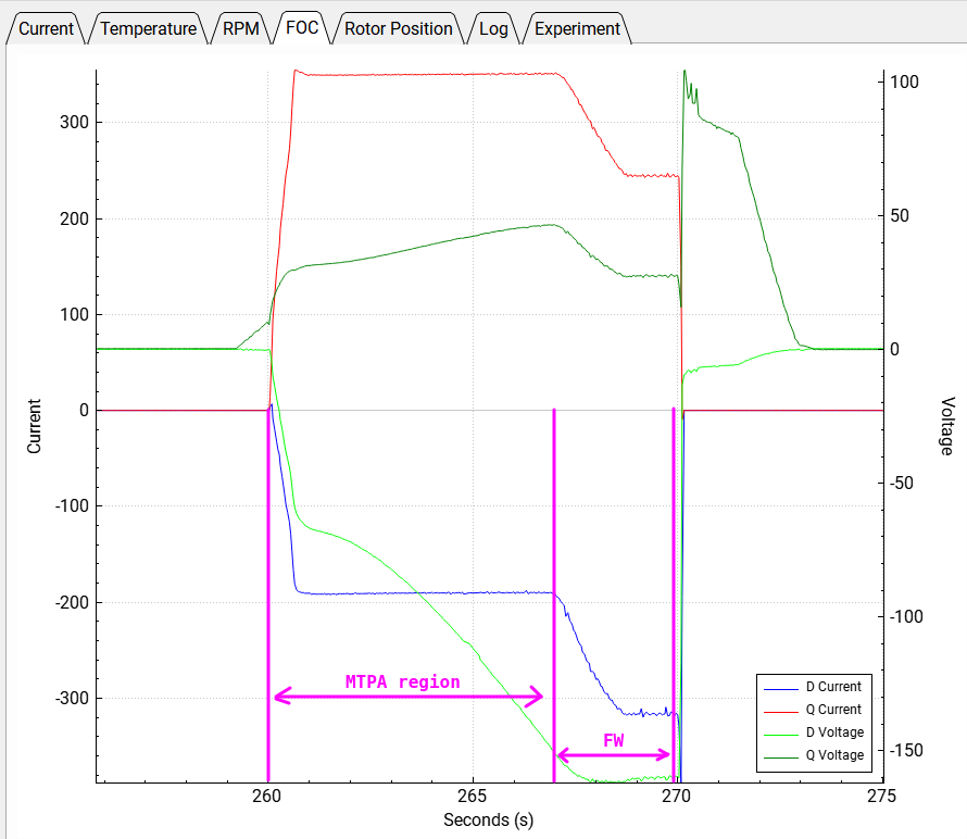
In this real time plot you care about Q current (red) and D current (blue). A simpler FOC controller would keep D current at zero, but we can see how D current increases to increase the net torque in the MTPA region.
That's a light testing at 400 phase Amps, but we are regularly testing all our firmware improvements at 800A and have well exceeded the 100kW target even at lower than rated battery voltage.
A typical 800A dyno run looks like this:
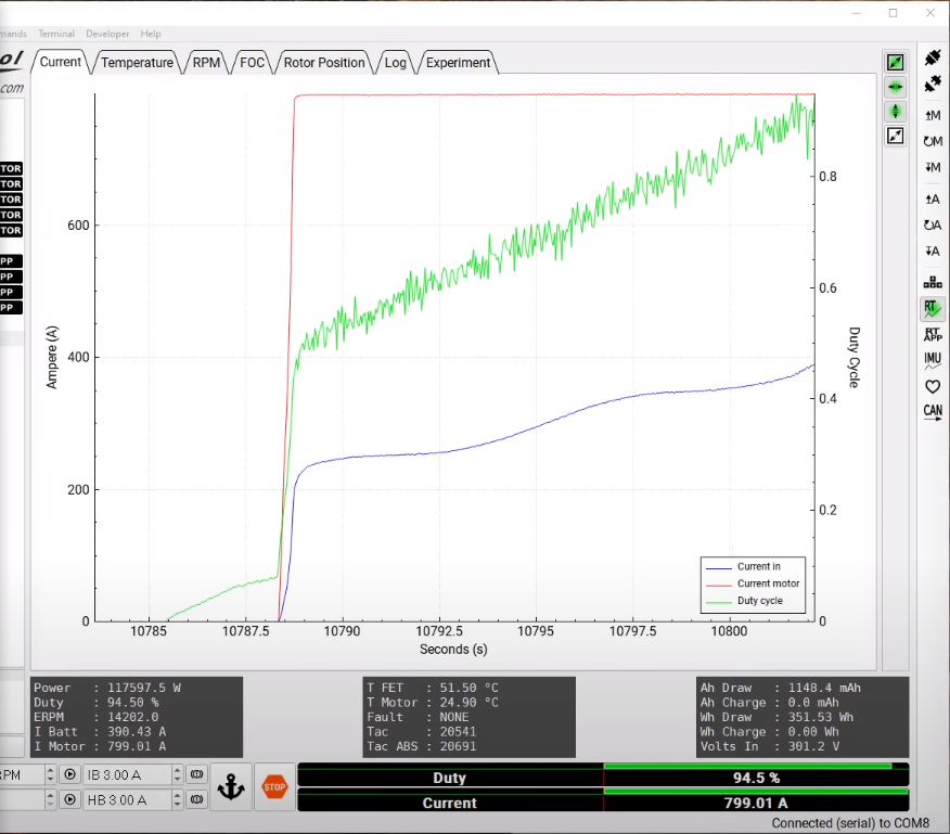
And a sneak peak at a dyno run, with the motor under test on the right side:
So that's it, VESC can now make a better use of IPM motors
Discussions
Become a Hackaday.io Member
Create an account to leave a comment. Already have an account? Log In.