 Squonk42
Playing audio is absolutely part of the gaming experience!
So for a retro gaming console like the FunKey, we need to have a decent audio playback, despite its lilliputian size.
By decency, we discarded the solution using a piezo-electric buzzer: these can get a loud sound in a small volume, but only at their resonance frequency, so the sound quality is extremely poor.
Turning back to the solutions used in modern smartphones as an example, there are 2 paths to consider:
- playing audio internally by the mean of speaker(s)
- playing audio externally by using headphones, with or without a cord
The speakers used in today's smartphones are rather sophisticated and achieve very good performance. However, these are using made-to-measure speakers and cavities, such that they cannot be found and reused as standard parts in a design like ours.
As for the external audio solution, we have a problem: the FunKey is so small that it is not possible to integrate an audio jack to connect headphones! And despite our search, there is no simple and small enough way to use Bluetooth to output audio to cordless headphones either.
The best solution we have found consists in using a single tiny speaker from CUI CDM-10008, that is able to output 72 dB spl @ 1m from a 0.3W input power, with relatively modest dimensions: 10 mm diameter and only a 2.9 mm thickness.
Connections are not easy though, since this speaker is meant to have wires soldered to its pads, but we are trying to convert it into an SMT device in order to gain space in our small enclosure! We don't have a satisfying solution yet that is possible to use for mass production, we are still working on it!
Schematic
The resulting schematic is simple, as the Allwinner V3s already contains an analog stereo audio codec (coder/decoder): we only have to take one of its headphone output channel (left or right) and feed it to a mono audio amplifier.
We chose the PAM8301 chip because of its cheap price, good availability, its more than sufficient output power of 1.5W and its filterless operation, meaning that no bulky series capacitor is required to drive the speaker.
Here is the corresponding schematic:
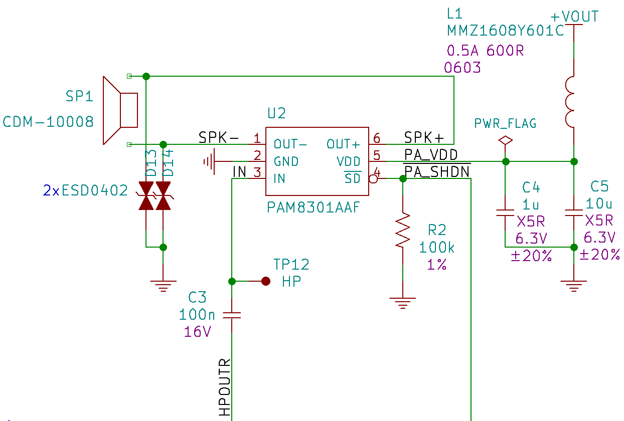
We chose the right headphone channel HPOUTR that is fed to the audio amplifier U2 through a DC-bias filter capacitor C3.
The audio amplifier /SD shutdown input is driven by one V3s GPIO, with a pull-down resistor R2 to disable the amplifier by default.
The audio amplifier power supply is filtered using a ferrite bead L1 in order to eliminate high-frequency digital noise, and decoupled by 2 capacitors C4 and C5, as recommended in the device datasheet.
The speaker SP1 is driven in differential mode in order to get the maximum voltage swing and thus the maximum power available for a given output current.
Two ESD protection TVS diodes D13 and D14 are added, since the speaker may be accessible to the user through the enclosure grid in front of the speaker.
Discussions
Become a Hackaday.io Member
Create an account to leave a comment. Already have an account? Log In.
Seems like any speaker is going to sound pretty pitiful at this size. And being ultra-portable there will probably be people nearby for it to bother as well. Do you think it will be possible to permanently install some earbuds by soldering the wires directly to the mainboard in place of the speaker? The wires can be pretty short since it will need to be held near your face for playing anyway, and with strategically chosen wire length and a bit of velcro on the lid, it ought to be possible to wrap them around it a few times and then stick the velcro over the wires to keep it all tidy when not in use.
Are you sure? yes | no