 Squonk42
LCD Screen
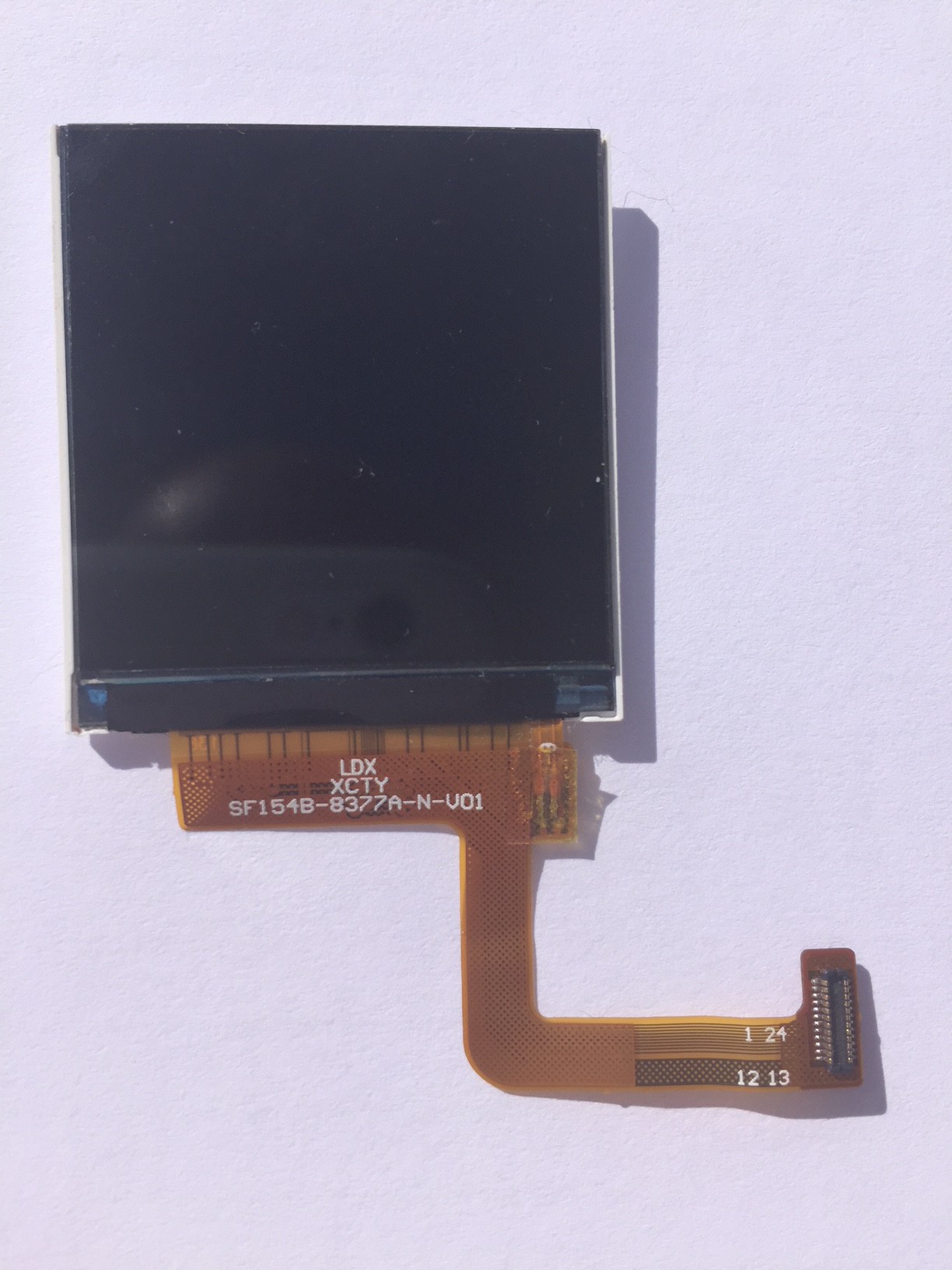
The chosen LCD screen for the FunKey console is awesome:
- 1.54" diagonal, 33.72 mm x 31.52 mm
- 240 x 240 pixels
- 262K colors
- wide view angle of 80°
- contrast 400:1
- IPS technology
- simple SPI interface, up to ~60 MHz
- ST7789V controller chip
Hinge
The FunKey console uses a foldable design in order to reduce the device size when not in use, and maximize both the screen and keypad size when playing. The screen flat cable must then go into the hinge, and in order to avoid too much stress that would eventually lead to broken cables, it must be "rolled" into it like a flypaper in order to divide the stress over the longest possible length.
Unfortunately, the stock LCD screen ribbon cable is not long enough. This is of course something that the manufacturer can customize, but this costs a fixed tooling fee of $800... We plan to go this way for mass production, but this sounds like a lot of money for the prototyping phase only.
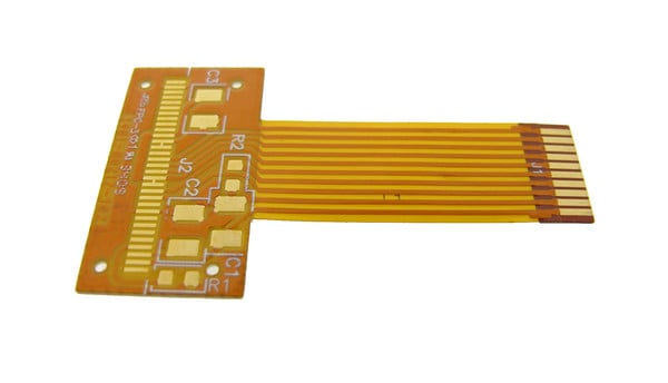
FPC Extender
So, we decided to use cheaper alternatives for our prototypes:
- for the Revision A, we used individually soldered thin enameled copper wires and an ultra small PCB placed into the hinge: definitely not something to use for more than 2 boards!
- for the Revision B, we decided to invest some money into a customized FPC (Flat Printed Cable) as we can get 5x FPC prototypes for ~$100 at PCBWay
The problem is: I never designed FPCs before ;-)
I got some basic hints from one of my colleague:
- the copper density must be as constant as possible
- the traces must use smooth curves instead of sharp angles to avoid tearing during flexion
However, a few questions remained unanswered:
- what material and thickness to use for the stiffeners?
- what material and thickness for the flex itself?
- which stack-up?
I decided to crawl the Web for more information, and here is what I found, I hope this may help some other PCB designers:
Stiffeners
Stiffeners are used over some parts of the FPC cable for various reasons, and I found this page very informative. Basically:
- stiffeners in FR4 (epoxy) material are added below components to protect solder joints: this is exactly what we will need for our connectors!
![]()
- stiffeners in polyimide (yes, this is the famous "PI" acronym that you meet everywhere, including on the SAEF screen datasheet!) are used to bring thickness to a given value in order to meet the ZIF (Zero Insertion Force) connector requirements
![]()
- aluminum or metallic stiffeners are used as heatsinks in order to dissipate temperature from power components
The stiffener thickness is variable, but is generally between 0.2 mm and 2 mm. I chose FR4 stiffeners with a 0.2 mm thickness as it is the thinnest, but also because this is the thickness for the original SAEF screen stiffener, too.
Flex
For the flex cable itself, I found this slideshow containing a lot of details.
I learned that:
- a flex is made up of Polyimide ("PI", aka Kapton which is a trademark from DuPont)
- Pyralus is another trademark from DuPont for the sandwich including the PI film, the glue and copper laminate, the glue and the PI "Coverlay" (for "Coating Overlay")
- the copper can be in rolled Annealed ("RA") form, or obtained by electro-deposition ("EP"), the former being more common and cheaper
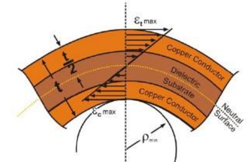
- for a single or double-sided flex, the minimum bend radius is 6x the total thickness, 12x when using more layers
![]()
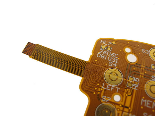
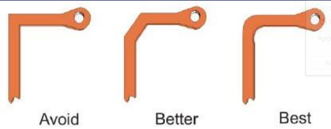
- indeed, using curved traces is better that sharp-angled ones!
![]()
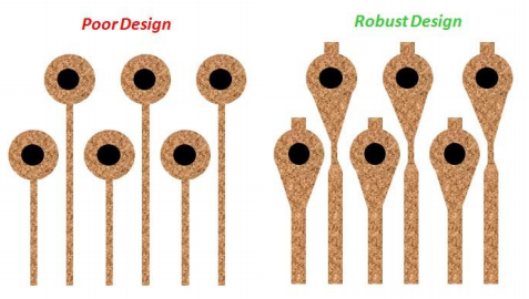
- vias should feature "teardrops" to avoid problems with the larger drill / copper / coating registration tolerances for FPCs
![]()
- a hatched ground plane is recommended in order to reduce weight and increase flexibility
With all these elements now clear, I decided to use PI with rolled-annealed copper foil ("RA") to reduce costs.
Stack-Up
For the layer stack-up and dimensions, I found these 2 links useful:
https://www.epectec.com/flex/material-stackup.html
http://www.asia1tec.com/goodies/FPC_material_datasheet.pdf
The second link shows a stack-up for a common double-sided FPC thickness (without the stiffeners) of 0.196 mm and provides the constitutive materials, for which I found the corresponding datasheets:
https://www.sas-electronics.de/downloads/FL_SF302.pdf
https://www.pcbglobal.com/files/SF302C%20Coverlay.pdf
Please note that with a SF302 0511210DR laminated PI core instead of the SF302 101820DR one, the total thickness lowers to 0.151 mm when keeping the same COverlay. This will probably be my final choice to achieve a greater flexibility.
Layout
Here is my custom layout. Please mind the gap in the hatched ground plane on the bottom side, which is designed to "guide" where the flexion (roll) should take place:
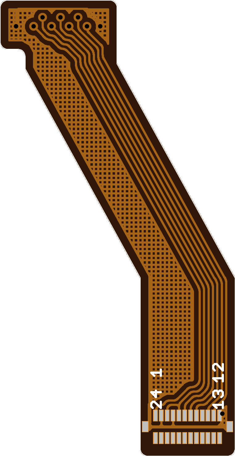 | 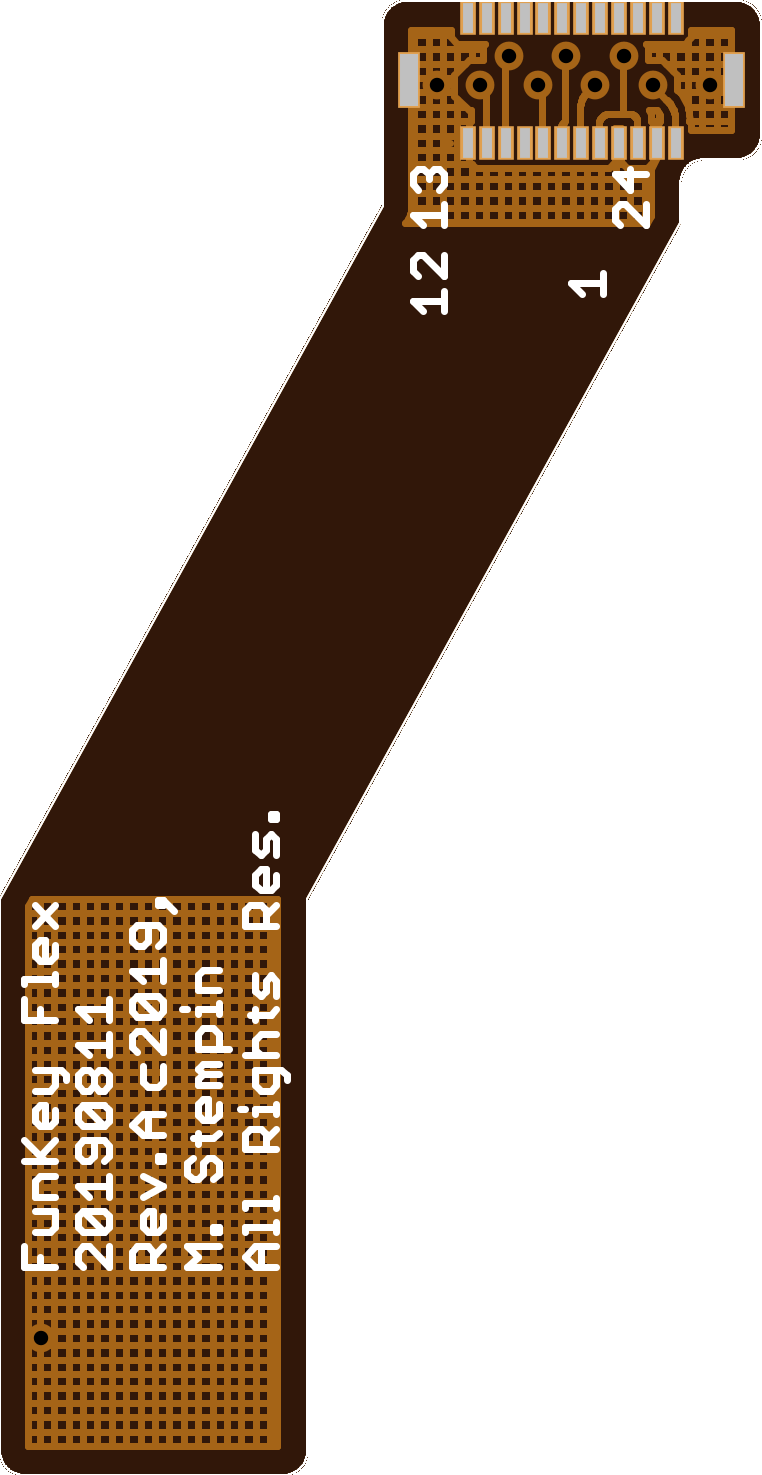 |
Discussions
Become a Hackaday.io Member
Create an account to leave a comment. Already have an account? Log In.