 Squonk42
SPI LCD Screen
One of FunKey's strong point is certainly its screen: in a chosen form factor of roughly 45x45x15mm (1.75x1.75x0.6"), it has to be comfortable enough to provide a good gaming experience.
If in theory this allows to shoehorn a 2.4" (diagonal) square screen, in practice, these screens are seldom square and more rectangular in shape.
Unless you are a large manufacturer and selling millions of devices, you are limited to using the screens that are available on the market, which most of the time were designed for a long-forgotten specific devices (think of PDAs, MP3 players, clam-shell phones, pods, etc.) and standard aspect ratio are either 5:3 or 16:10. Thus, for a given pixel technology, this results in rather standard screen sizes.
So the next size down is 1.8", but these screens tend to be quite thick and based on an old technology, so their typical resolution is rather limited @ 128x160 pixels: too small for gamers.
Still going down in size, you can find 1.5~1.55" screens with an interesting resolution of 240x240 or even 320 x 320 ("Retina") pixels, but most of them use a fast and complex MIPI DSi interface requiring a dedicated controller on the host side. These screens were popular as the screen used in 6th-generation iPods, but unfortunately, getting a retail CPU with a MIPI DSi interface is almost impossible.
Fortunately, we found this 1.54" LCD screen on AliBaba:
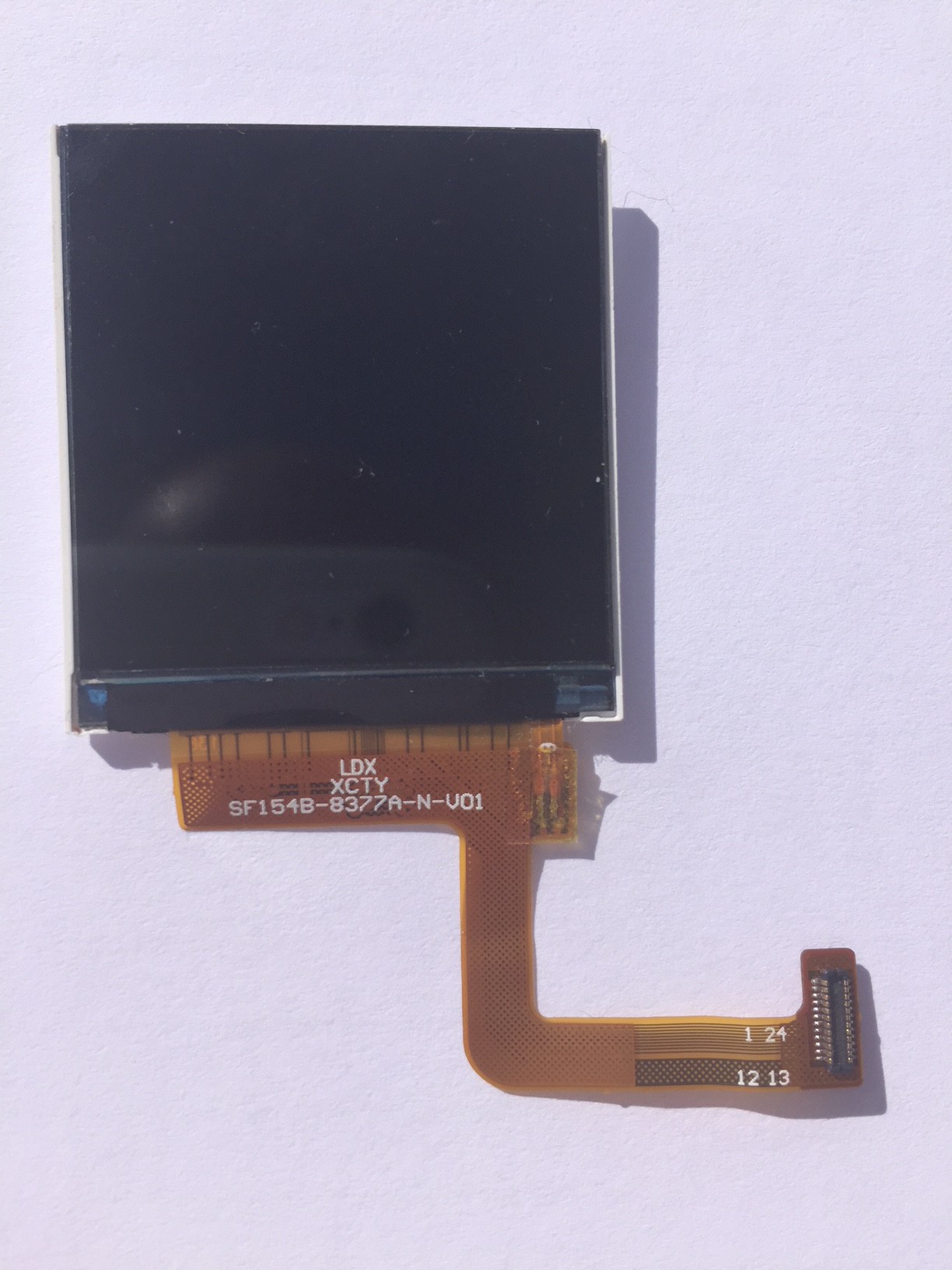
What makes this screen remarkable is its standard SPI interface, which like the MIPI DSi one, only requires a few wires and thus a narrow flex cable, easy to roll into a hinge.
This 1.54" display has 240x240 16/18-bit full color pixels and is an IPS display, so the color looks great up to 80 degrees off-axis in any direction.
Be careful though, as in order to achieve a 30 fps @ 240 x 240 pixel resolution in RGB666 (3 bytes / pixel), this requires a ~40 MHz SPI clock rate. Once again, we were fortunate as both the V3s CPU and the screen built-in controller (a Sitronix ST7789V) support this high clock speed (after checking with the manufacturer and despite the controller datasheet specifies only a serial clock cycle (Write) of 66 ns or 15 MHz!).
We were even luckier as its backlight consists in 3 white LEDs in parallel and not in series, such that no additional step-up DC-DC converter is required, as a standard 3.3V / 60 mA (typical) power supply is sufficient. Of course, we won't be able to drive this current directly from a CPU GPIO and the backlight will require an additional transistor to interface to the LCD backlight.
Its flex cable requires a mating Hirose 0.4 mm pitch DF37NB-24DS-0.4V dual row SMT connector, out of which only one single row is actually used.
Schematic
The schematic is thus quite simple:
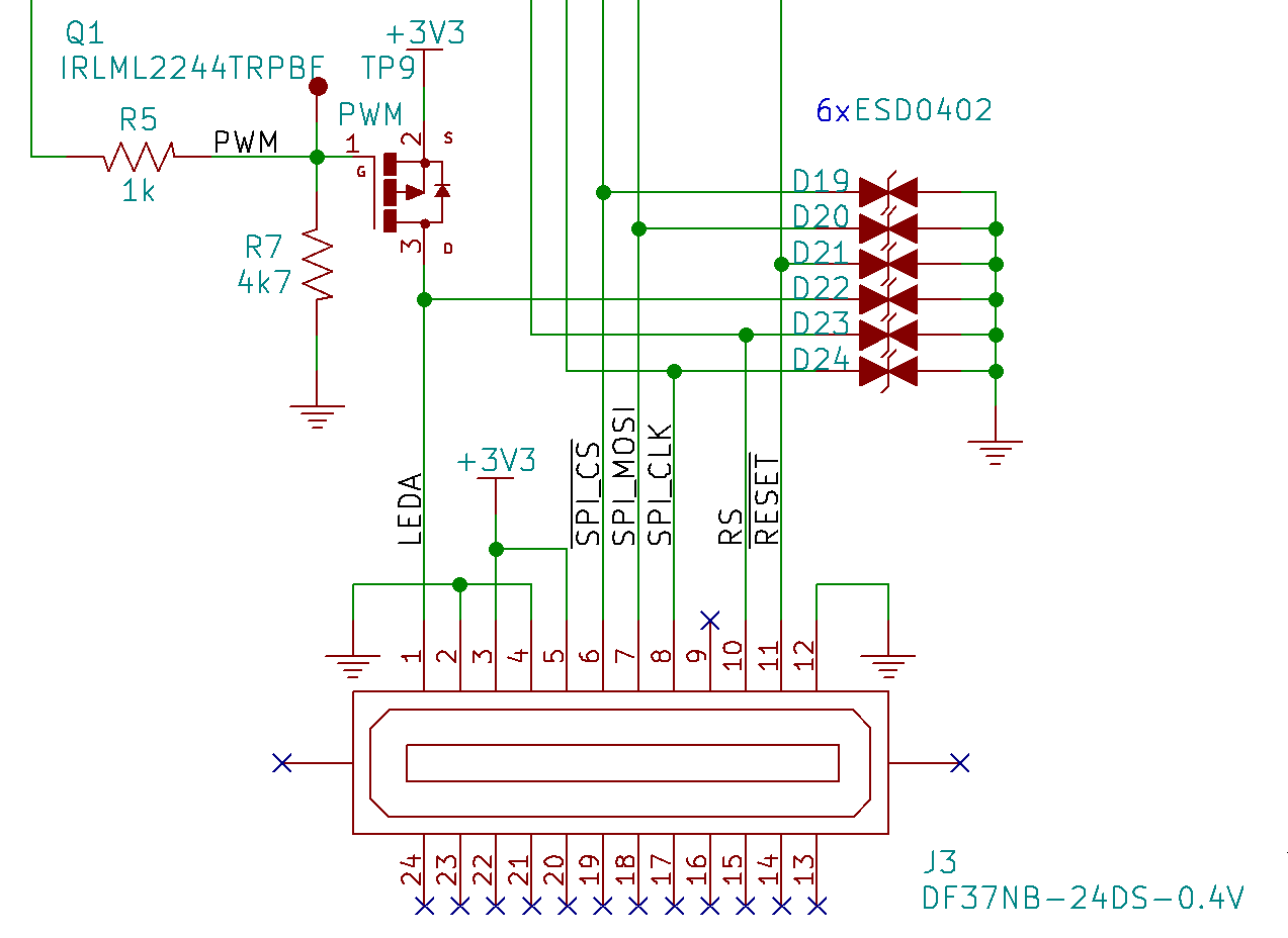
The main component is of course the Hirose screen connector J3, with the following signals:
- LEDA: the backlight LED Anode connection (+)
- GND
- +3V3 power supply
- /SPI_CS: SPI Chip Select
- SPI_MOSI: SPI Master Out / Slave In
- SPI_CLK: SPI Clock
- RS: LCD-specific Register/Memory Select (or Data/Control Select)
- /RESET: LCD Reset
All data signals feature an ESD TVS protection diode D19-D20, and except for the power supplies and LEDA + /RESET signals, all signals are directly connected to the V3s CPU's SPI interface, so there is not much to say about these.
The /RESET signal is currently tied to the PMIC PWR_OK output, but in a future revision, we plan to change this so it is instead controlled from a CPU GPIO pin.
Backlight PWM
The backlight control requires a few more components: a MOSFET-P transistor Q1 and 2 resistors R5 and R7 to provide its polarization, more on this below.
As the backlight LEDs cathode (-) pin are directly tied to GND within the screen, we need to drive these LEDs "from the high-side", i.e. between the +3V3 power supply and the LEDA pin, so a MOSFET-P transistor is necessary:
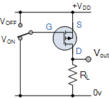
As we want the backlight to be on by default, we need to drive it to GND by default: this is the role of R7. The role of R5 is then to make sure that -Vgs is driven below its threshold voltage and turns off the transistor when the CPU drives a GPIO high.
As an ultimate sophistication, we can drive the backlight from the CPU using one of its PWM built-in controllers with a varying duty-cycle, thus controlling the LCD backlight brightness accurately.
Discussions
Become a Hackaday.io Member
Create an account to leave a comment. Already have an account? Log In.