Goniometron the Flexinator is a wireless wearable capable of measuring amount of finger movement and range of motion (over 1 hour and 1 day epochs).
Shame on you for thinking this would be way cooler if it were a data glove for playing games and stuff. That's the failure of the technological utopia talking, don't listen to it.
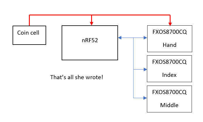
To quantify finger movement and measure range of motion, Goniometron will use three integrated accelerometer/magnetometer pairs. The first inertial sensor pair will be a reference sensor located on the back of the hand, and the other two will be located on the first segment of the index and middle fingers. To estimate joint angles, Goniometron will estimate the orientation of each sensor and then estimate the orientation of the two finger sensors relative to the one on the back of the hand.
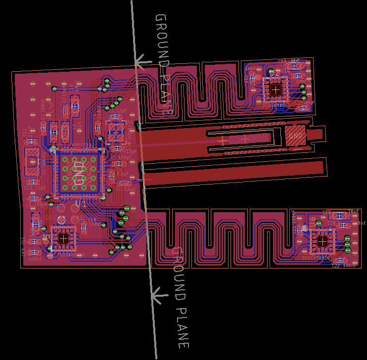
Since the sensors need to be able to move relative to one another, they will be mounted on a flex PCB. I am not sure that this is going to work the way that I want. It seems likely that it would make more sense to use the separate PCBs with cables running between them, but if it does work then it simplifies the design significantly.
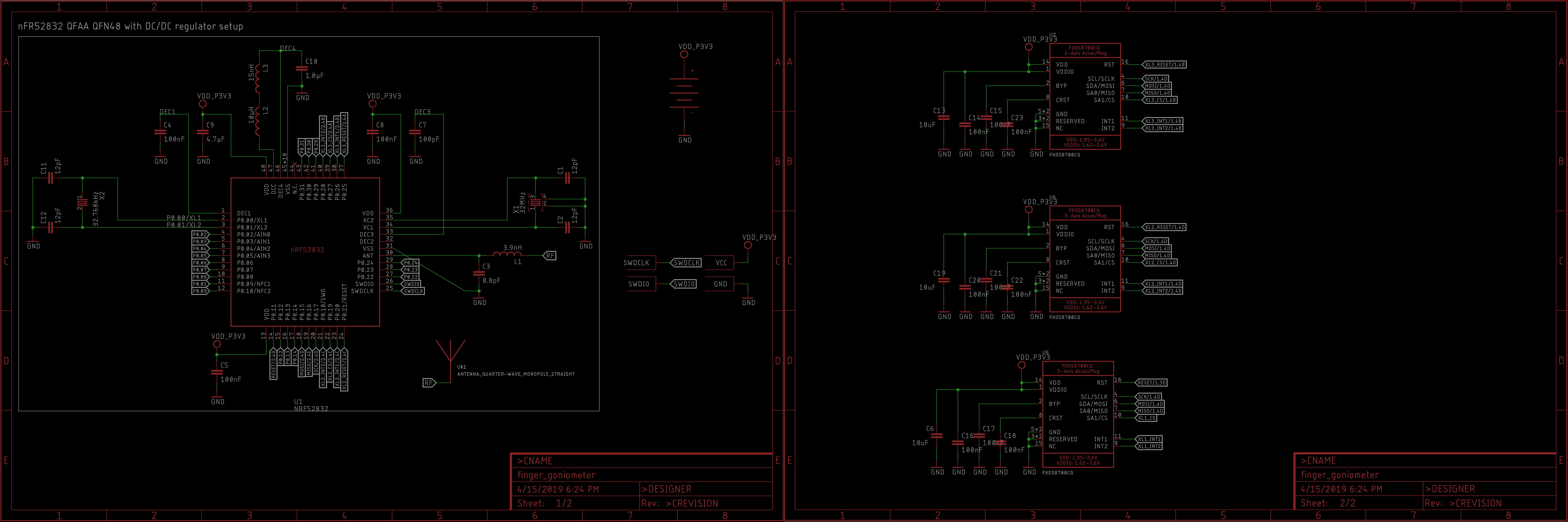
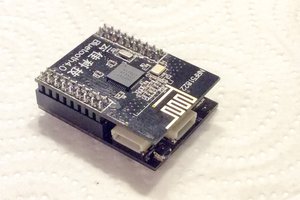
The three sensors will be controlled by an nRF52 (an arm-cortex m4 with an integrated 2.4gHz radio developed by Nordic Semiconductors). Another advantage of the flex-PCB is that it will probably be much easier to isolate the antenna for the radio from the ground plane.
To keep things simple, Goniometron will be powered by a non-rechargable coin cell battery. the microcontroller has internal voltage regulators, so we can power it straight from the coin cell battery. It should even be able to tell us when the battery voltage is running low.
 Lukasz
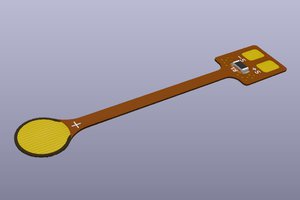
 Jose Ignacio Romero
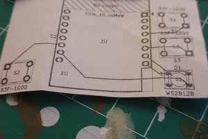
 Discombobulated8080
 PCB designer