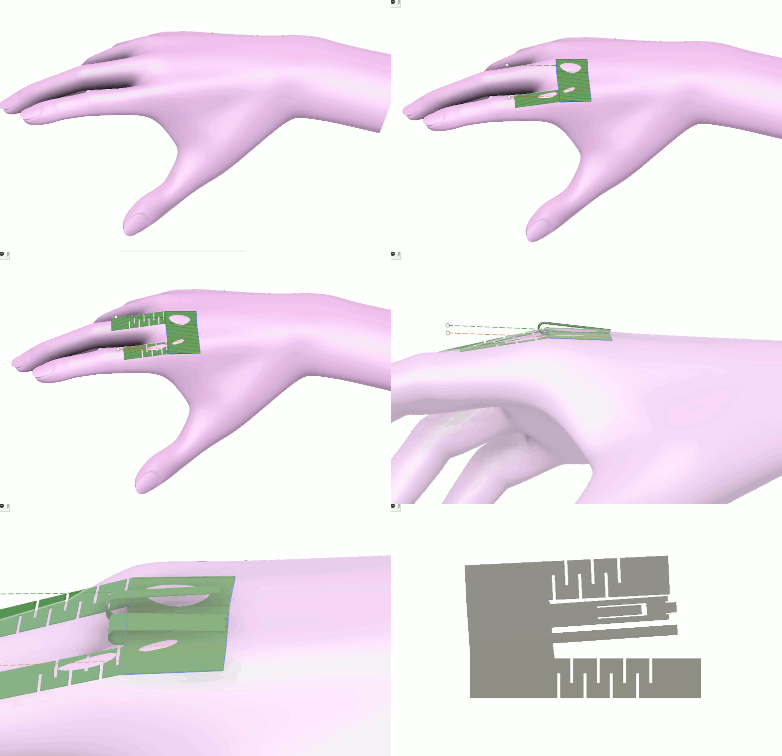
Normally for a project like this I would start by designing the PCB, but for this particular project, form factor is very important. The PCB needs to fit onto the back of the hand and the sensors placed over the fingers need to have the freedom to bend with the fingers.
I will be using a flex-PCB for this project, and since the value of flex-PCBs comes from their ability to confirm to 3 dimensional structures, it makes sense to design the outline of the board using a 3d cad tool instead of a normal 2 dimensional PCB cad tool.

The sheetmetal tools in fusion 360 are perfect for designing 3 dimensional structures that need to be able to unfold into 2 dimensional designs. I sarted by making a quick sketch for the back of the palm and then extended flanges out for each finger.
I added serpentine cuts into the finger flanges to try to give the board more freedom to bend laterally, but I am not sure they are going to work well enough. If they don't, then the flex PCB will probably tear when the wearers fan out their fingers.
Between the two fingers, I extended out two more sections for the battery and the antenna. Unfortunately, I had to put the flange for the antenna very close to the flange for the battery. It would have been better to put it off to one of the sides, but that would have doubled the overall size of the design. For now I think it makes more sense to see whether putting the antenna near the battery causes serious problems.
Once all the key features were in place, I used the "unfold" command in fusion 360 to create a flat pattern for the design, which I exported as a .dxf file.
Because fusion 360 and Eagle are both owned by autodesk, it is very simple to import a dxf file generated by fusion 360 into Eagle. Oh, wait, no. It actually doesn't work at all. I had to open the .dxf file in inkscape and re-save it before importing it into eagle using the import-dxf.ulp. I also had to replace all of the curved segments with straight segments. After doing that though I was able to import the outline I made in fusion 360 into the dimension layer in eagle.
Discussions
Become a Hackaday.io Member
Create an account to leave a comment. Already have an account? Log In.