The angles made the a particularly tricky board to lay out because of the angles. To route the traces on the angled flanges, I measured the angle in fusion360 and rotated the entire board to align the angled flanges with the x-axis. Eagle had a bit of roundoff error that would create design rule violations when I rotated the board back after routing the traces, so I had to micro-adjust the traces (or more often the board dimensions) to correct them.
I suspect that bending the antenna might change its behavior - I will have to test that once I have the boards - I should probably add in a U.FL connector to make testing a bit easier.
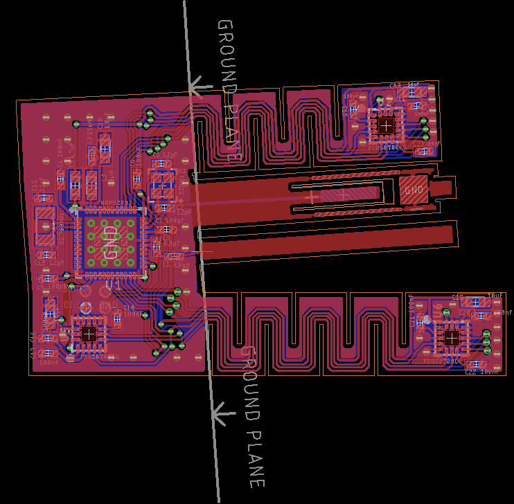
normally for a 2 layer board I would stitch the top and bottom ground planes together with vias along the edges, but 1) I didn't have a lot of space for that, 2) the weird angles made it difficult to get even spacing, and 3) I was worried that putting a bunch of vias right next to the edges that I was going to be bending might cause the board to tear instead of bending. Instead of stitching the ground pours together around the edges, I just stitched them together in a grid.
Discussions
Become a Hackaday.io Member
Create an account to leave a comment. Already have an account? Log In.