Hello everyone! Again : )
Previously I figured out how to achieve a real efficiency gain, v1.2 circuit board had various limitations, as well as a few mistakes. Summer ended, now I have less time for my own projects, but I gain experience developing other stuff and I can implement it here!
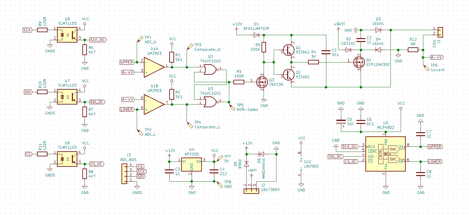
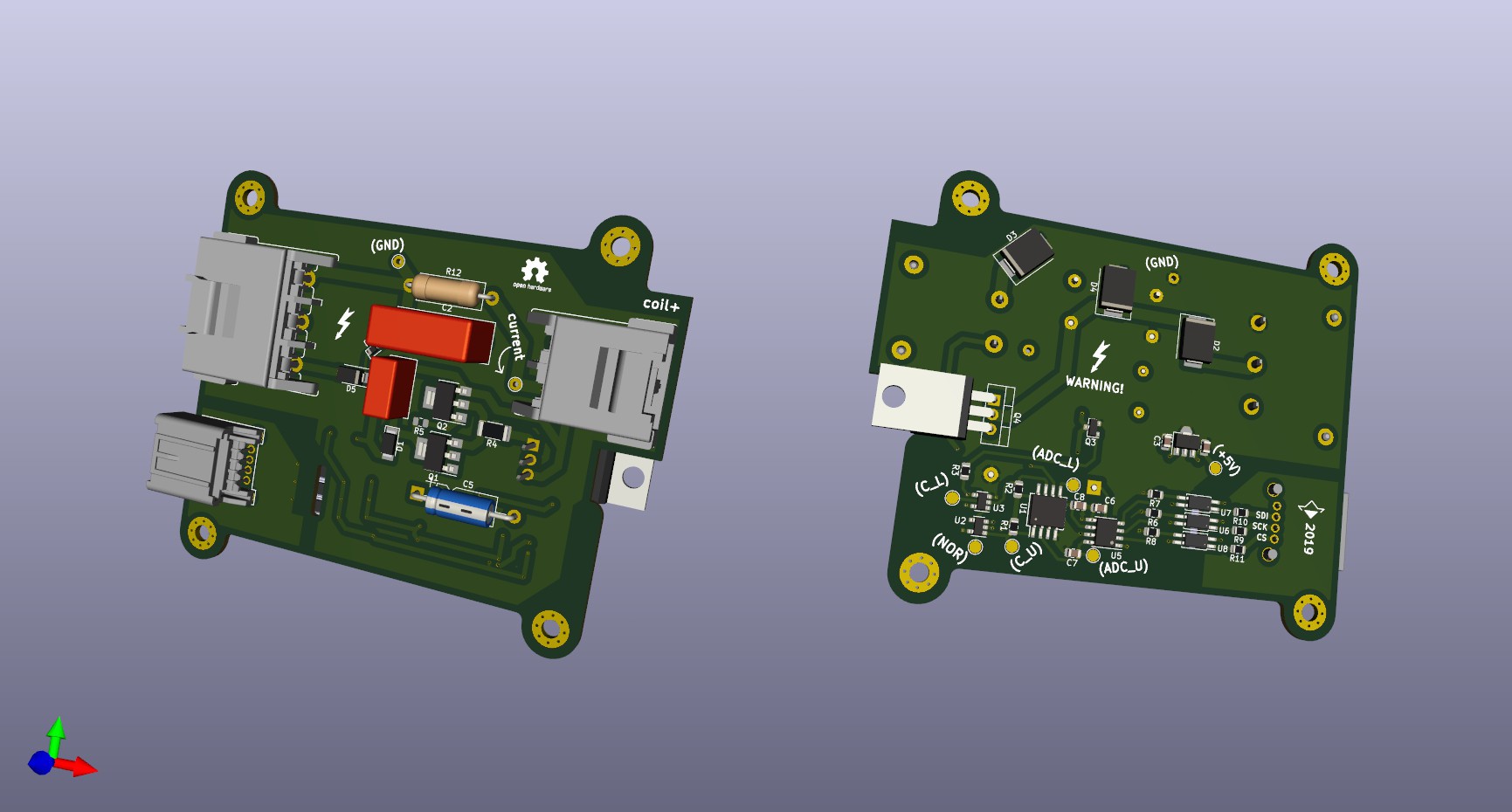
I reconsidered some aspects of a board, and that is what I have now: This time I chose distributor of electronic components who works internationally instead of our local shop, so I had a wider range of components to choose from! What's why now board features automotive connectors for example, way better than "PC" connectors stocked in our shops : )
I added a DAC, sending PWM signal from MCU constantly isn't reliable at all, as well it gets affected by inductance of wires coming to a control circuit, e.t.c. e.t.c. Instead of that, we can use SPI, to connect great amount of independent boards. And I'm not choosing I2C, 3bit addresses for individual DAC's cannot give enough freedom if you're willing to connect 30 board at some point.
As this iteration is suited to work with high voltages (300V max), optocouples are necessary to protect MCU, which can be quite expensive. I have high-side driver this time, it wouldn't dangle on wires somewhere aside of a board. Last time it confused me much, now I tuned this thing nicely and it should work well. Finally, you may notice test points - they should be very helpful for maintenance.
 Overall, design is much more robust now, can't wait to see it working, I have plans for that one. Now it should cope with power needed to my linear actuators and I really want to experiment with transformers and BLDC motors, this board is suitable for them too, as it is a general-purpose EM field controller.
Bringing down heat dissipation of a conventional BLDCs gonna be fun :D
P.S. PCB ships for about 30 days, components... I think they have same delivery time, so next update should be in December. Time passes by so fast! However, do you remember concept of charge-based electromagnet from previous log? It seems that I figured out how it possibly can be done, if it works, next update is much closer than December and it would be amazing. Why? Hm... )
 CapitanVeshdoki
Discussions
Become a Hackaday.io Member
Create an account to leave a comment. Already have an account? Log In.