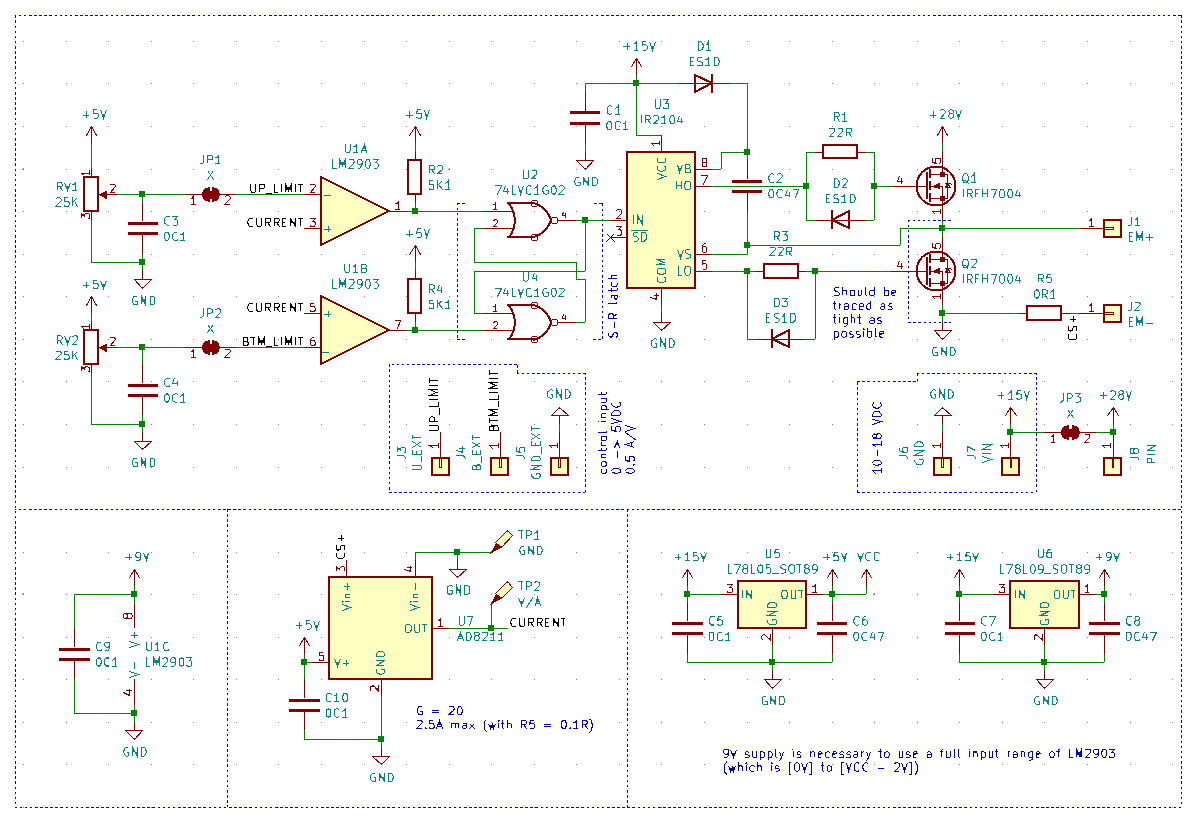
It seems it's gonna be optimal to freeze that project for a while, but beforehand I decided to make a summary of some sort: that EMF retention technique worked well, making schematics and PCB available is gonna be great for someone willing to experiment with it. Also, previous versions were kinda clumsy, I've learned a little from other stuff I designed recently That version won't high voltage very much, main focus was onto providing lowest possible resistance near Q2. 40V IRFH7004 were a best choice from what was widely available in my country. Higher voltage means higher efficiency, but hey, most of benchtop power supplies are 0-30V or close to that, should be fine : )
Using solder jumpers you can choice between using two PSU (up to 28V) and one PSU (18V max) arrangements. Also, there are two potentiometers to adjust upper and bottom current limits, which you can disarm in similar fashion, by desoldering JP1 and JP2, to use it with some external controls if you wish (0.5 amps/volt, 0->5VDC with a stock 0.1ohm current-sensing resistor)
Oh, and AD8211 is used there to provide somethat better on-state resistance capabilities, as it provides 20x gain. Anyway, typical electromagnet has a resistance around 15ohms or so. I chose 0.1ohm since lower values are NOT widely available here (that is funny), it's not like I'm a fan of 1W THT resistors or anything , )
 It should look something like that. Important to notice, that PowerPAK-8 housings were not devoted for high-current performance, but only for extremely low channel resistance. Actually, Q1 can be any el cheapo mosfet, only Q2 is critical, like that it looks cooler, though, ahaha
Would take a couple months to get that from China, if it works properly - gonna upload gerber files e.t.c. for public use. With a little explanation on what it does, to rewind that here are 2 posts available:
Post 1
Post 2
 CapitanVeshdoki
Discussions
Become a Hackaday.io Member
Create an account to leave a comment. Already have an account? Log In.