 CapitanVeshdoki
Yesterday, I managed to solder everything in place!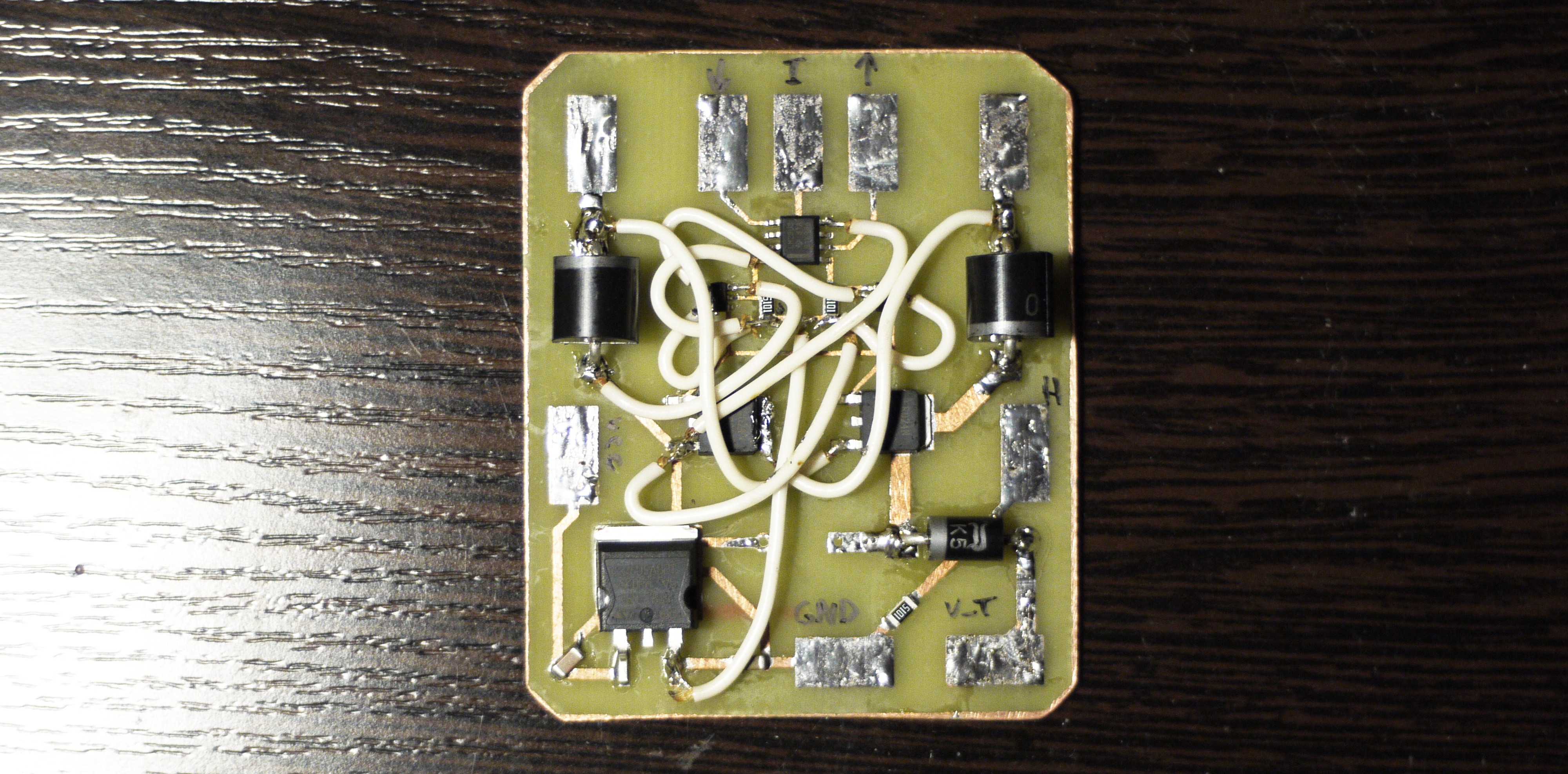 Looks quite tangled, next time I would think twice before counting on wiring that much, maybe two layers worth hardship to fabricate, it gets complicated then it's needed to change something there with this amount of not-so-solid wiring above components :D
When everything connected it looks like that: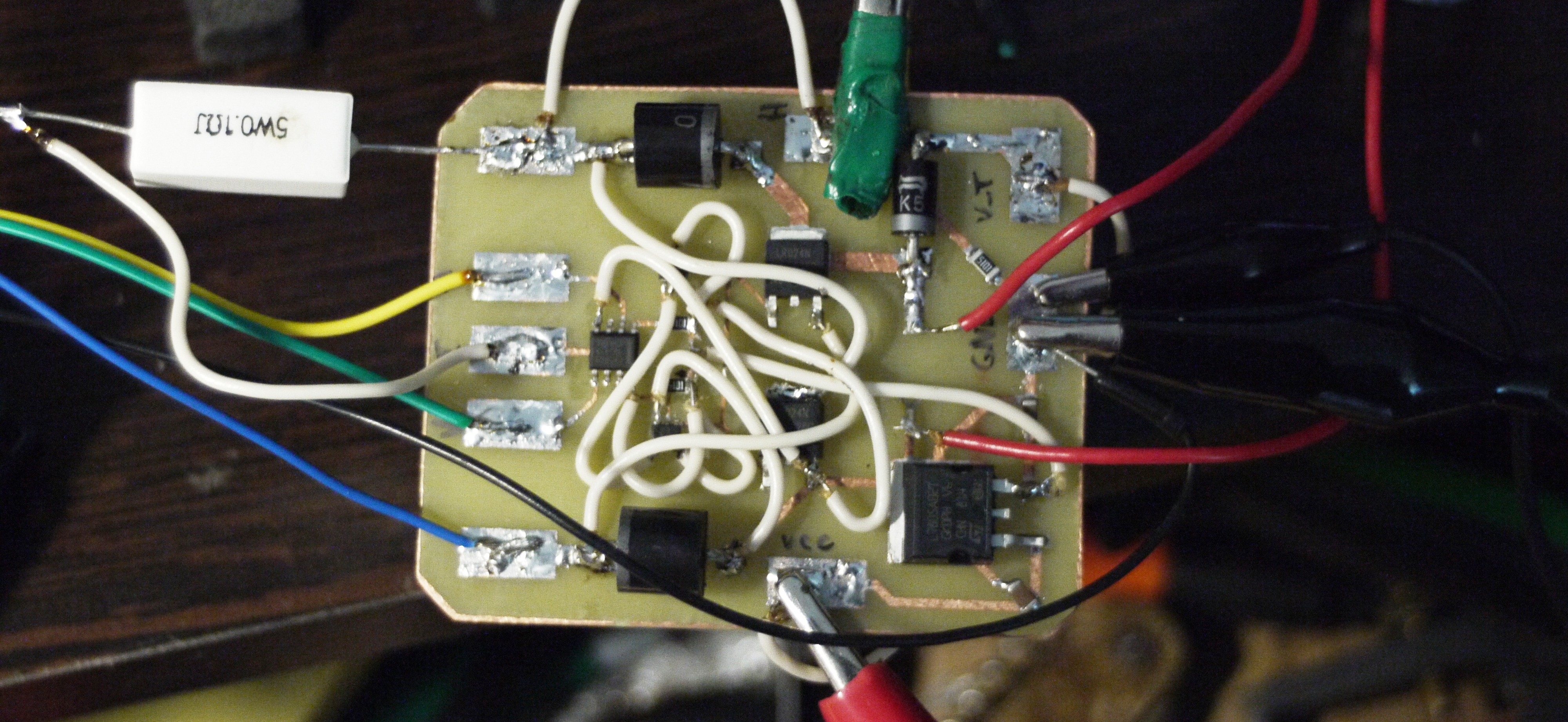 V_TRG (see previous logs with schematics, if curious what is it) here connected directly to the power supply, reference voltages connected to analog voltage outputs of an Arduino with great hope to play with parameters afterwards... But ---
But then I realized what something went wrong. Well, board consuming 0 current (according to my 5A PSU analog indicators of course), I can feel a slight field around the electromagnet, but too little. Then I connected an oscilloscope (1ms/div):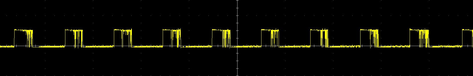 So there it is! This is a voltage which goes from S-R latch to the gate of transistors. So far looks not that bad (except of 30% duty cycle)
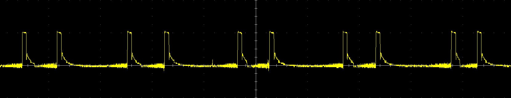 And there fun things started! This is a voltage on I_COIL input which theoretically represents current on electromagnet, however... It is 10V/div, so as I tried to measure voltage on the 0.1 Ohm resistor connected in serial with a coil - this would mean, what in some time periods there is around 100 Amps. Looks pretty awkward, isn't it?
 Well, it is. Because then I connected oscilloscope directly to the resistor, there wasn't anything like that.
That means, that I must figure out how to measure current (representing energy of field) correctly without damaging energy-retaining process.
Trivial task, but It may require two independent grounds to prevent leakage of electrons. I hope it wouldn't be necessary (because I'm lazy! ahaha)
Discussions
Become a Hackaday.io Member
Create an account to leave a comment. Already have an account? Log In.