 CapitanVeshdoki
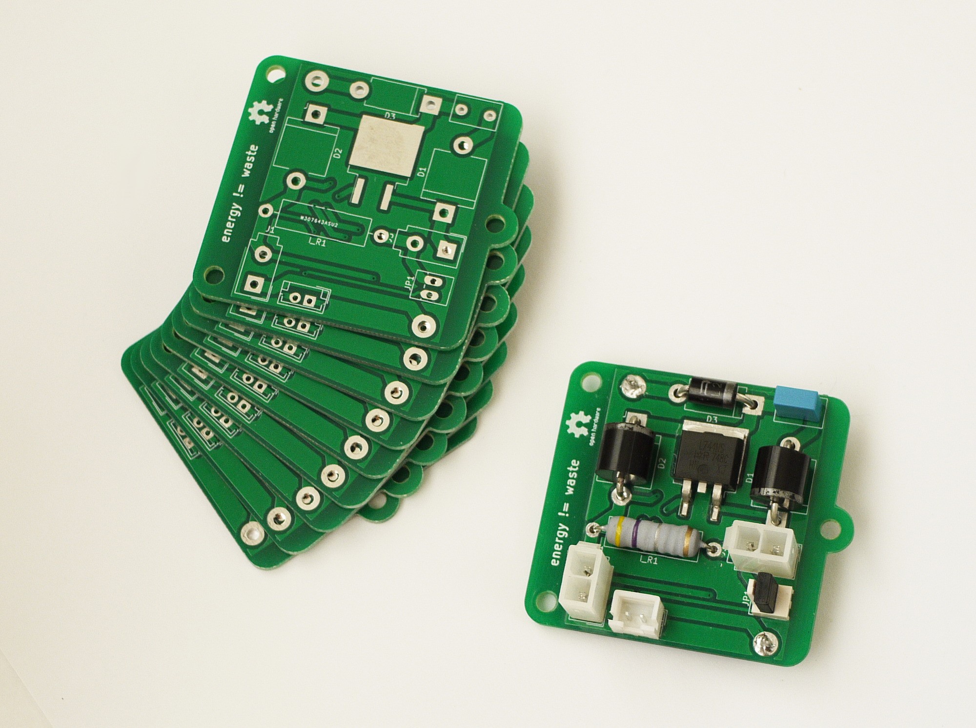
Hello everyone. After a couple weeks I've got my PCB's and assembled first one.
Big thanks to PCBway, never seen so much enthusiasm from a PCB manufacturer
Quote: "power of chaos" - such a pearl! It was a fun time talking with you, guys : )
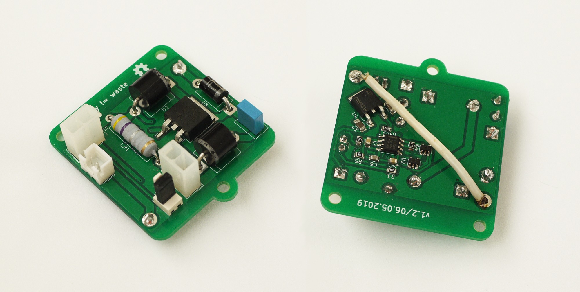
^ wire here - bridges VCC and V_TRG, leaving possibility to use high voltages in coil circuit
without bad outcomes for the little 5V linear stabilizer, used to power up logic circuitry!
I was able to control it via MCU (Arduino) directly, hooray!
First of all - never trust PWM->Voltage article on Instructables. It's totally wrong - instead of using 0.1uF capacitor in Low-Pass filter, I highly recommend 10uF, it is fixed in project files which I gonna upload in future, however, I think I should mention it
Everything works?
 Well, not that simple! All circuitry, responsible for a giveaway-reserve energy cycle works fine - it generates control signal in right time and then sends it to the gate of MOSFET
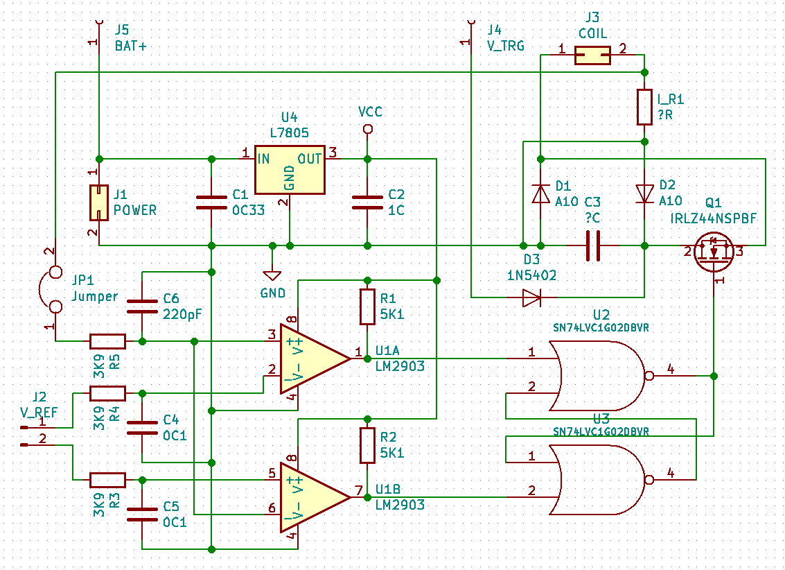
And then strange thing happened - IRLZ44NS (that mosfet) fails to output more than 5V:
- source voltage - is OK, much greater than 5V
- it obviously not from logic elements, how they can output half-amp currents? no way!
- stabilizer heats? not at all, but MOSFET does
FETs were connected similarly back in the days, then I tested previous version. If anyone has a theory why that can happen - would be happy to hear, because I have no idea at the moment
Here is schematics again, if needed:
 Magical thing! Not unsolvable, anyway : )
[probably, I just messed up soldering, who knows]
Discussions
Become a Hackaday.io Member
Create an account to leave a comment. Already have an account? Log In.