 CapitanVeshdoki
Yep! Complete discharge guide!
I don't want to repeat that was there previously anyway, so - links.
Theoretical parts:
- Part 1 (how efficiency works while you charge an electromagnetic field)
- Part 2 (why discharge time matters and how it affects heat dissipation)
- Part 3 (that one was half-wrong, but heat dissipation part is likely to be true, read carefully)
- Part 4 (what affects discharge time)
This time I want to make a finishing pass on discharge topic. It looks like that:
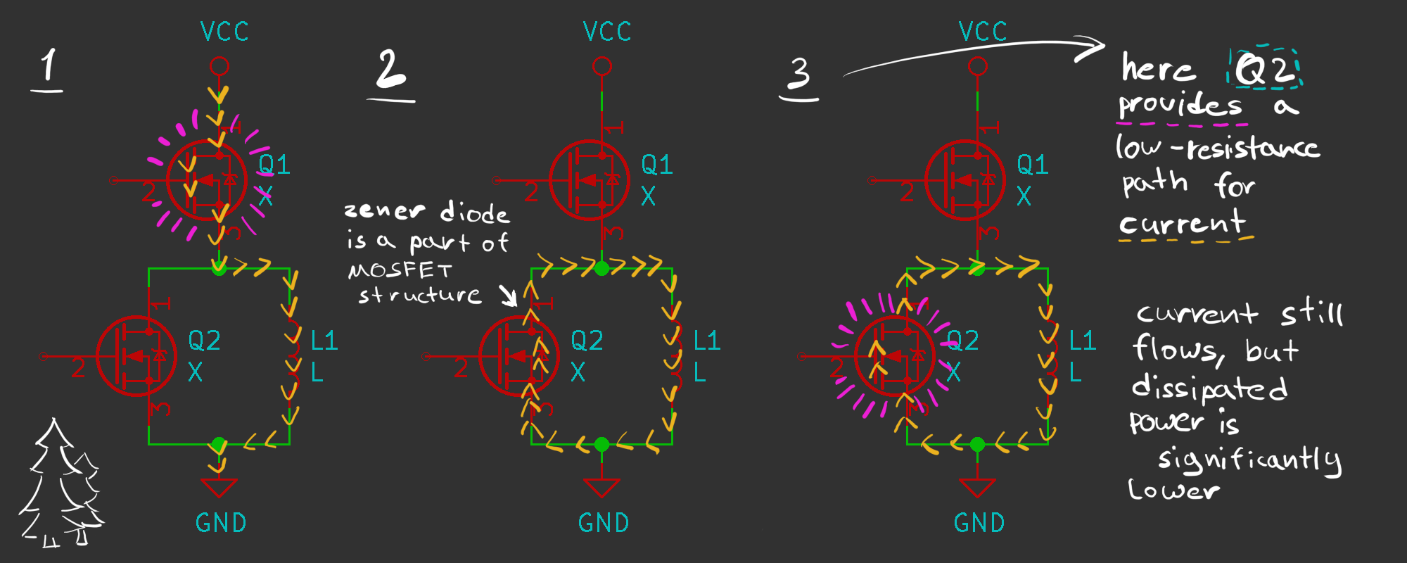 In theoretical Part 4 we came to a conclusion, what voltage drop affects discharge time significantly. Must-read, but simplified - coil tries to produce constant current while discharging and it's a very easy task if voltage drop is minimal. One approach is to use a diode, however, 0.4V is pretty high. And that is where MOSFETs come to play, acting as a low-resistance load.
Zener diode in MOSFETs structure is very helpful, since it can handle current until FET opened completely.
That's why this process has 3 stages and not two.
For example, we have 1A of current, conductive channel provides 10mOhm, U = I*R, voltage drop using this method is only 0.01V, 40 times smaller than what we have on a diode! There is a room to play, in different conditions channel shows different resistances. That's what I've got with a random transistor as proof of concept:
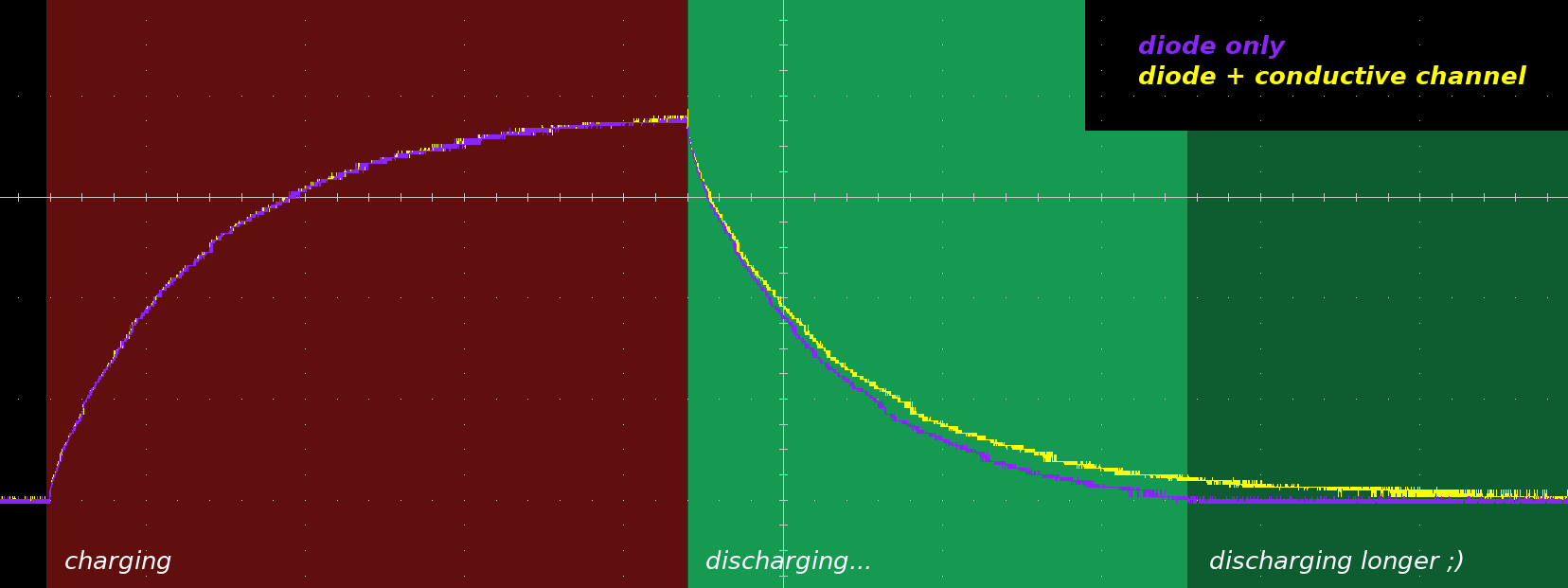 As you can see, it discharges about two times slower. It might be not very obvious, since discharging curve is really steep at the start, however, looking at the end of discharging process - advantage is pretty clear.
To replicate this results you only need two N-Channel MOSFETs and one high/low side driver to control them. Also, it would be great to use new DirectFets, since they provide very little resistance. Resistance is a main point there.
Funny enough - everything, that was there during charging process, like current-sensing resistors connected in series e.t.c., doesn't make any difference on a discharge - it's a part of what is being discharged, not a load.
Overall, that scheme is component-friendly, as long as you not trying to open Q1 and Q2 at the same time, shorting VCC to GND completely. There should be some sort of protection logic from that in case of control unit malfunction, it certainly would be on a next versions of control boards, but for test purposes... Why bother , )
P.S. Looking forward to some low-rpm or stall-shaft tests in future
P.P.S. I made additional attempts to conquer EM fast charge without high voltages, but for now with no results.
Fast charge & slow discharge ideal loop isn't closed yet, but now we are 50% closer! Hooray : )
Discussions
Become a Hackaday.io Member
Create an account to leave a comment. Already have an account? Log In.