 CapitanVeshdoki
Next logical step - is to couple theoretical findings with BLDCs, it is fun, educational and even useful at some point! In previous update that was a brushed motor... Pretty unfortunate - it's hard to imagine worse enemy than brushes with that approach.
I started to develop an experimental BLDC controller and imagine my surprise when I realized that circuitry, mentioned in previous posts, fits there ridiculously well! People, familiar with BLDC controllers, would probably notice that there is not much to change. Of course, specific control methods required and some hardware tweaks also, but hey, it's pretty neat : )
Generally speaking - there are high/low side FET's connected to each phase of BLDC coil, therefore there is an opportunity to shortcut coil from GND to GND via that. Or from VCC to VCC. Providing low-resistance path for a current, low voltage drop and so on... (topics from previous posts)
It's pretty pricey to implement analog current-control for each phase (thanks to DACs, low resistance and preferably hall-effect current measuring ICs, logic e.t.c.) - in this iteration, I decided to use old-fashioned way, outsourcing computational power and commands from an external MCU. Not the most elegant solution, neither a reliable one. Let's hope, that it would work without occasional fireworks.
Compromise is to use onboard timer and only ON/OFF signal to switch coils would be sent externally, however it would be a tedious process to make it on one layer board, with all required logic IC's. Simplified everything to a maximum degree possible, with one current sensing IC for all 3 channels:
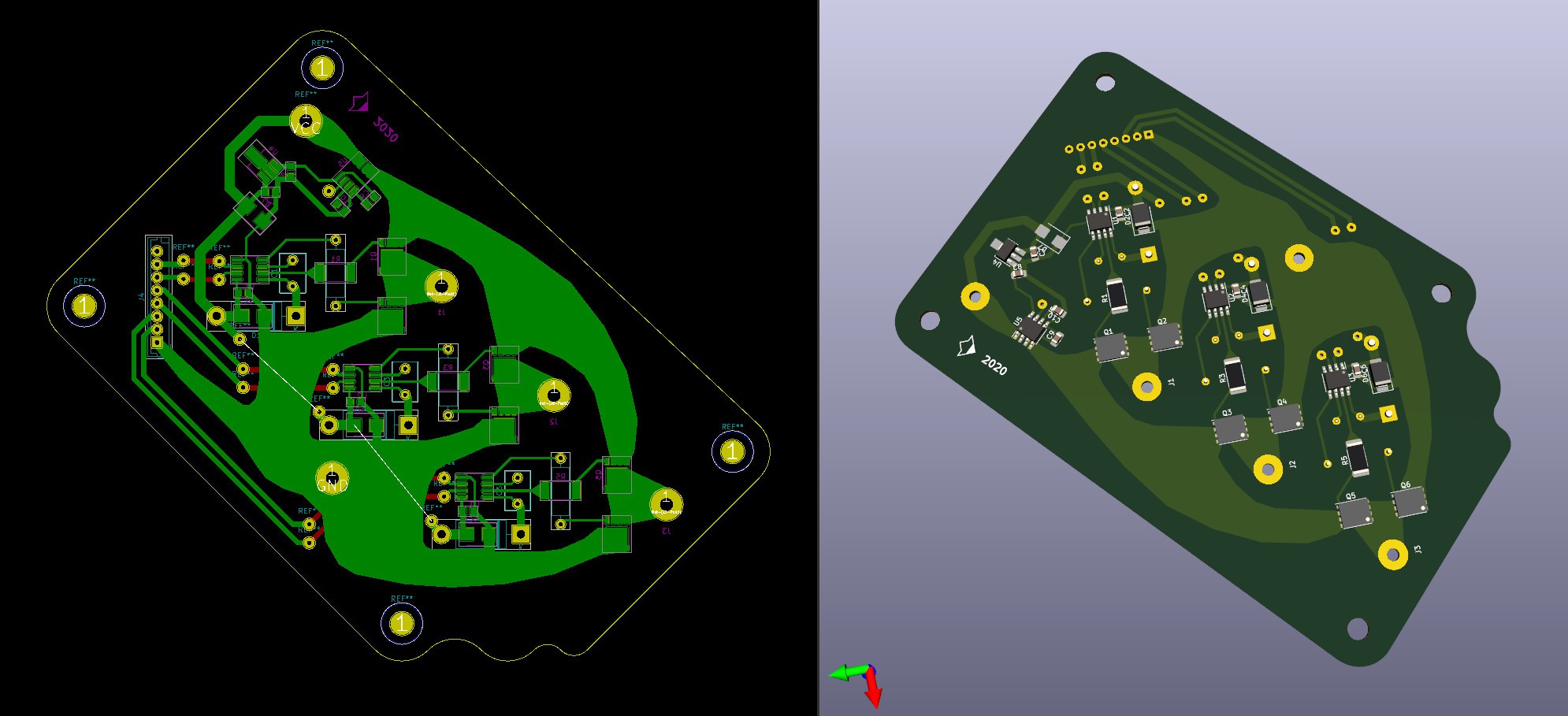 Had lot of fun tracing that stuff! Aside of queer shape, it should have a damn good resistance and heat dissipation properties. Inductance should be less as well.
Not sure, that I gonna manufacture this one soon, so there is a room for corrections.
I'd like to make traces which go from drivers to a gates wider, as I see it now
(there are interesting 4A source/sink MOSFET drivers)
P.S. And that is our test subject!
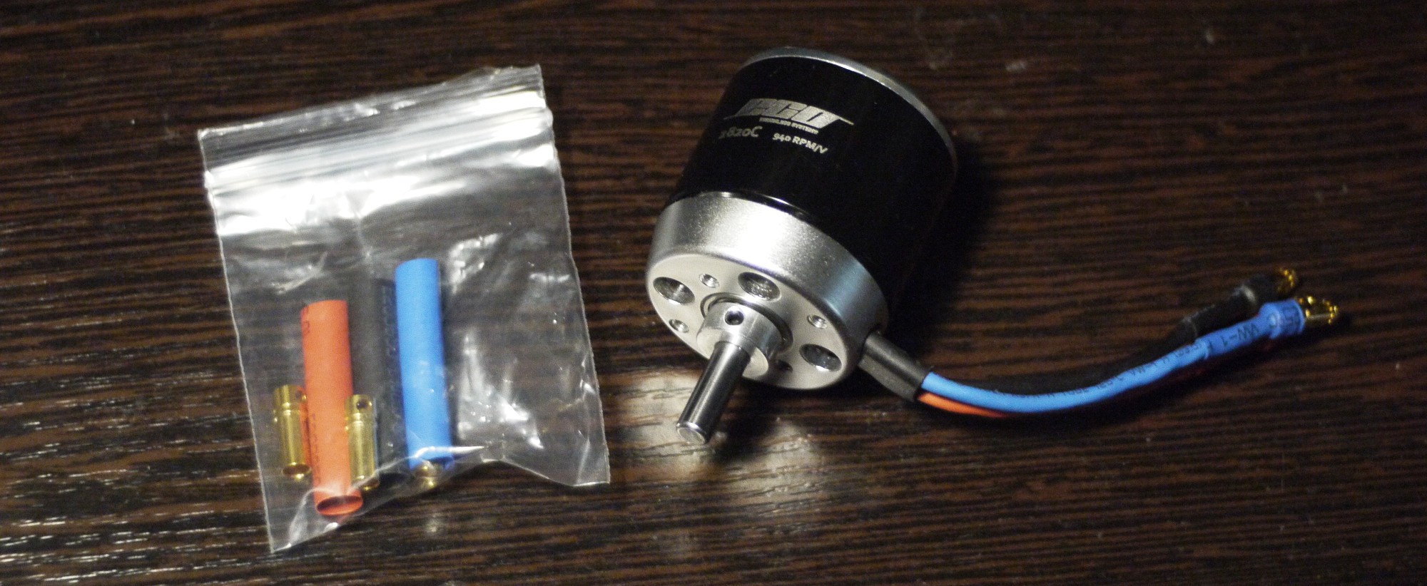 Motor has something around 30mOhm resistance, according to a manufacturer. Curious how it would play out, generally - low resistance would be a benefit, but with MCU-controlled board I'm pretty concerned about switching frequency. It's really easy to get sky-high currents that way x)
Discussions
Become a Hackaday.io Member
Create an account to leave a comment. Already have an account? Log In.