 James Holley
New PCBs are in, time to start soldering on components!
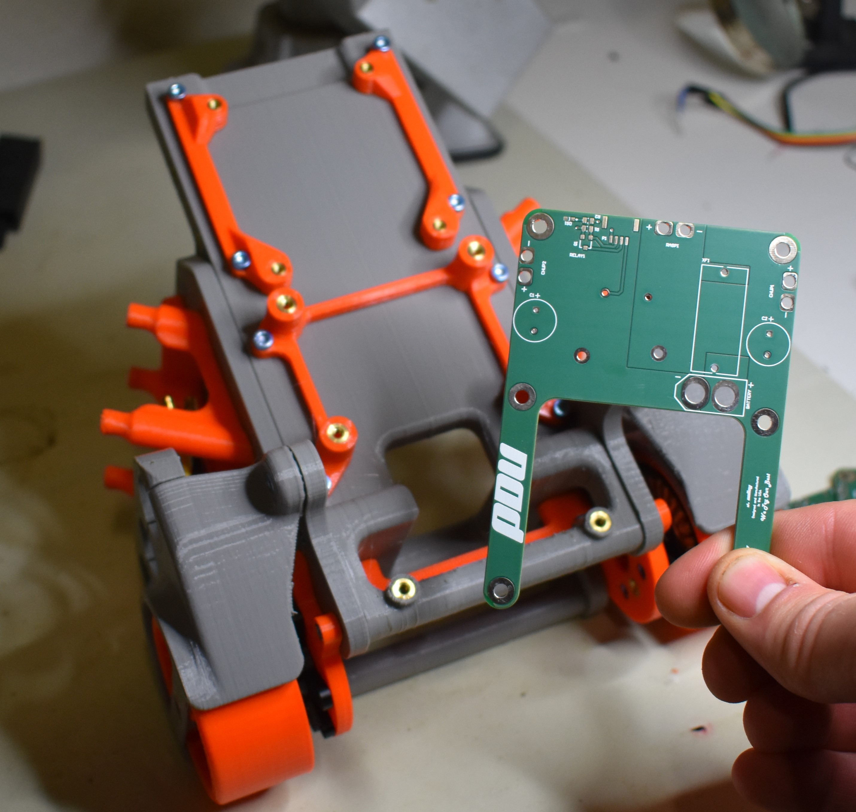
The board we're going to cover in this post is the PDU (Power Distribution Unit).
When it comes to LiPo batteries, I always try to stay on the safer side of things when I can, so the main components are an inline fuse and relay. The fuse we are using right now is rated to 15A - probably way more amperage than we need, but it will shut off power in case something short circuits. The relay will be used so that a signal from our on-board computer (Raspberry Pi) will be required to power the motors. This is nice just in case Bobble Bot takes a spill or the computer loses power, we can cut power to the wheels so our day doesn't get any worse. Other than that, the PDU just gives us a couple of nice connectors from the battery to boards we want to power - there's not much to it. The schematic is posted below for anyone that wants to take a closer look or offer any pointers.
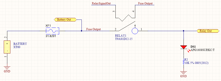
I included a LED so you can see when the relay is closed and power is passing through - don't mess with the bot while the power is hot!
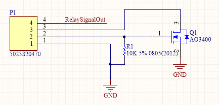
This is a connector and transistor circuit that completes the relay - pin 2 is connected to the Raspberry Pi GPIO and completes the circuit through the MOSFET. Pins 3 and 4 can be connected through a switch if you want an additional check on power going through the relay.
So now... I've chosen some SMT parts for the resistors, transistor, and LED. Even though these parts are a little trickier to solder, they have some good advantages. SMT parts are usually cheaper than through hole parts when buying in bulk, so you can save some money down the line if you know you are going to use a lot of them. If you are ever planning on getting your boards manufactured and assembled, SMT parts are the go to - through hole parts have to be soldered by hand, so you will have to go SMT at this point. SMT parts take up less board space and they don't stick through the bottom. This can be helpful for keeping interference with mechanical mounting to a minimum. And, if you have a little practice, they are not to difficult to solder yourself! I use a simple technique to help me solder them down - I usually go with 0805 components or larger to make the job easier.
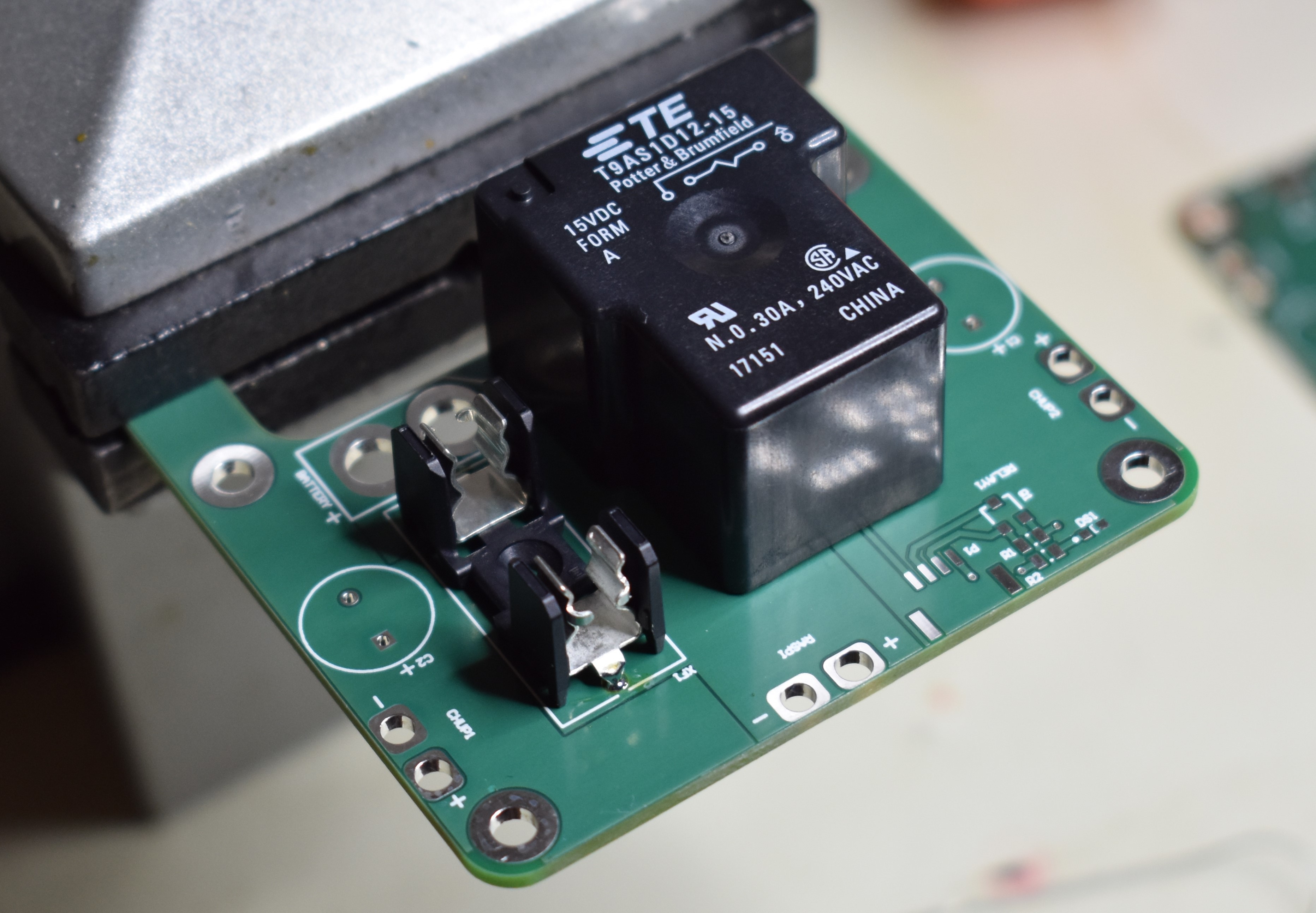
I've soldered in my fuse and relay - time to go after the SMT parts to the bottom right of the picture.
 The first step is to get the resistor on the board and to fill one of the two pads with solder. The other pad is kept clean. Make your life easy - the right pad is soldered here because... well.. I'm right handed, so that's the hand I hold the soldering iron in. Soldering SMT can be a little delicate, so make sure you set yourself up for success.
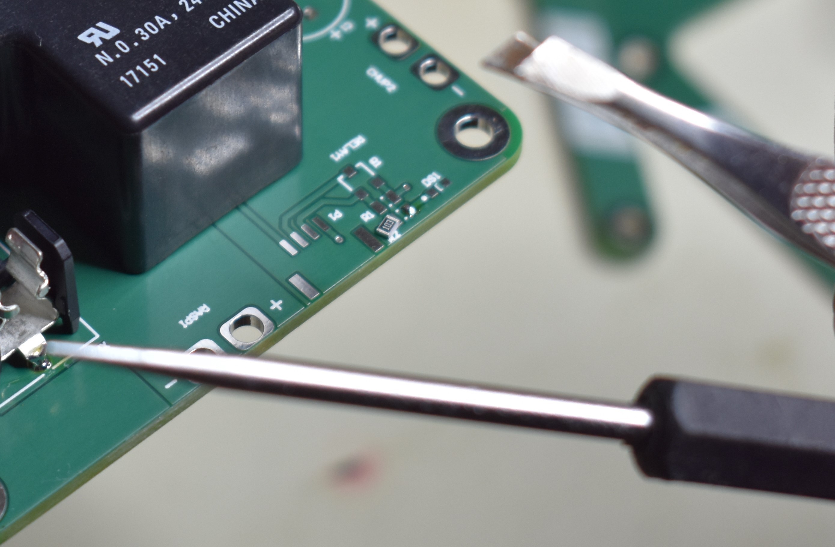
I have two go to tools for the next step - a probe and a pair of tweezers. Which one I use depends on the location of the soldering and how big the component is. For smaller components, a straight probe to push the SMT part is usually more helpful than trying to grab it.
Heat up the solder on the pad, and push the part into place - make sure that the part is flush with the board. A trick I usually use is to hold the part in place with the probe or tweezers and remove the soldering iron first. Wait for the solder to solidify, and you are good to go.
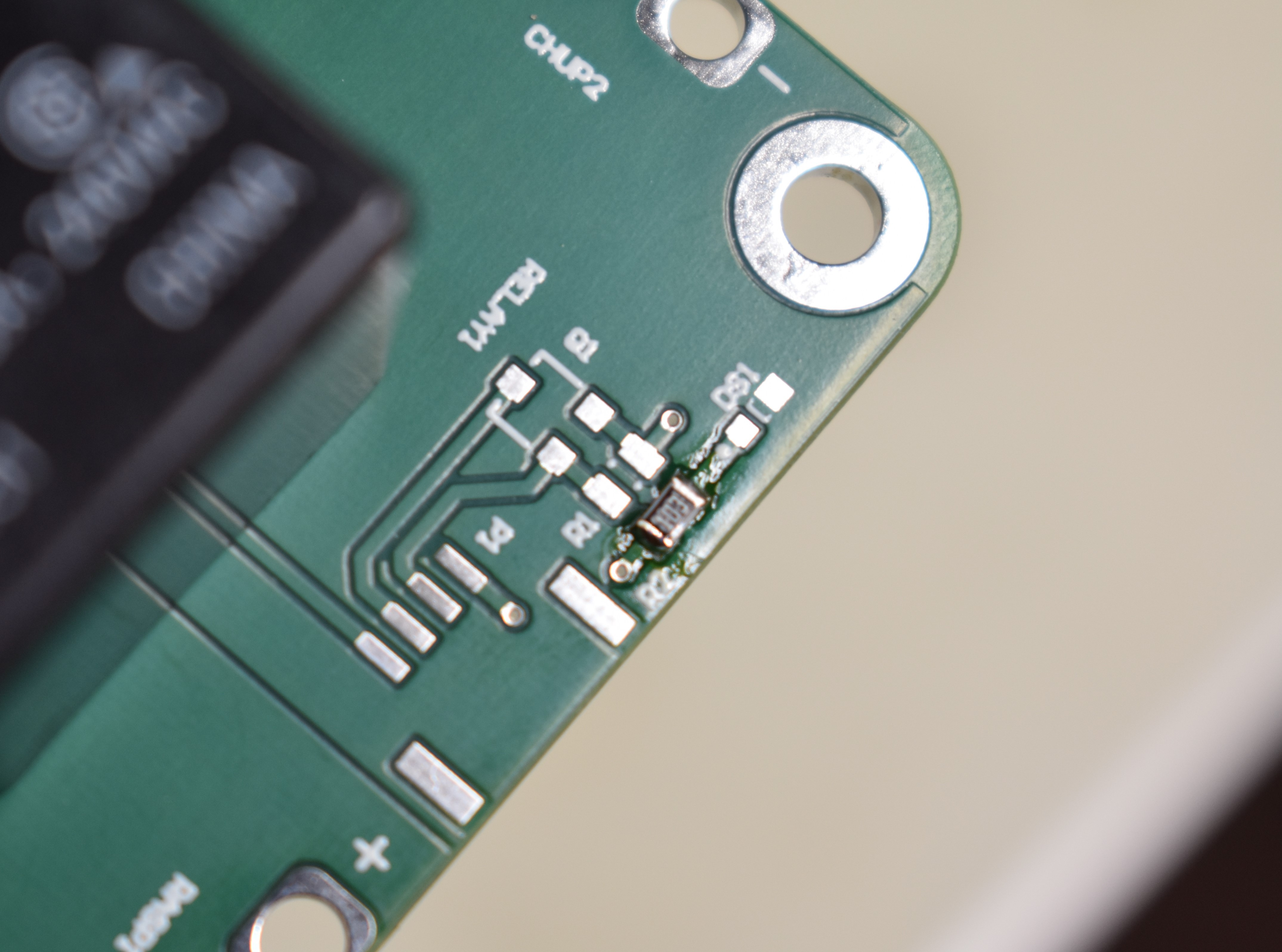
Once one side is soldered down, you can move to the other pad to complete the job. Here's a picture of the finished resistor.
And there you have it! After that its just rinse and repeat until you get the final product:
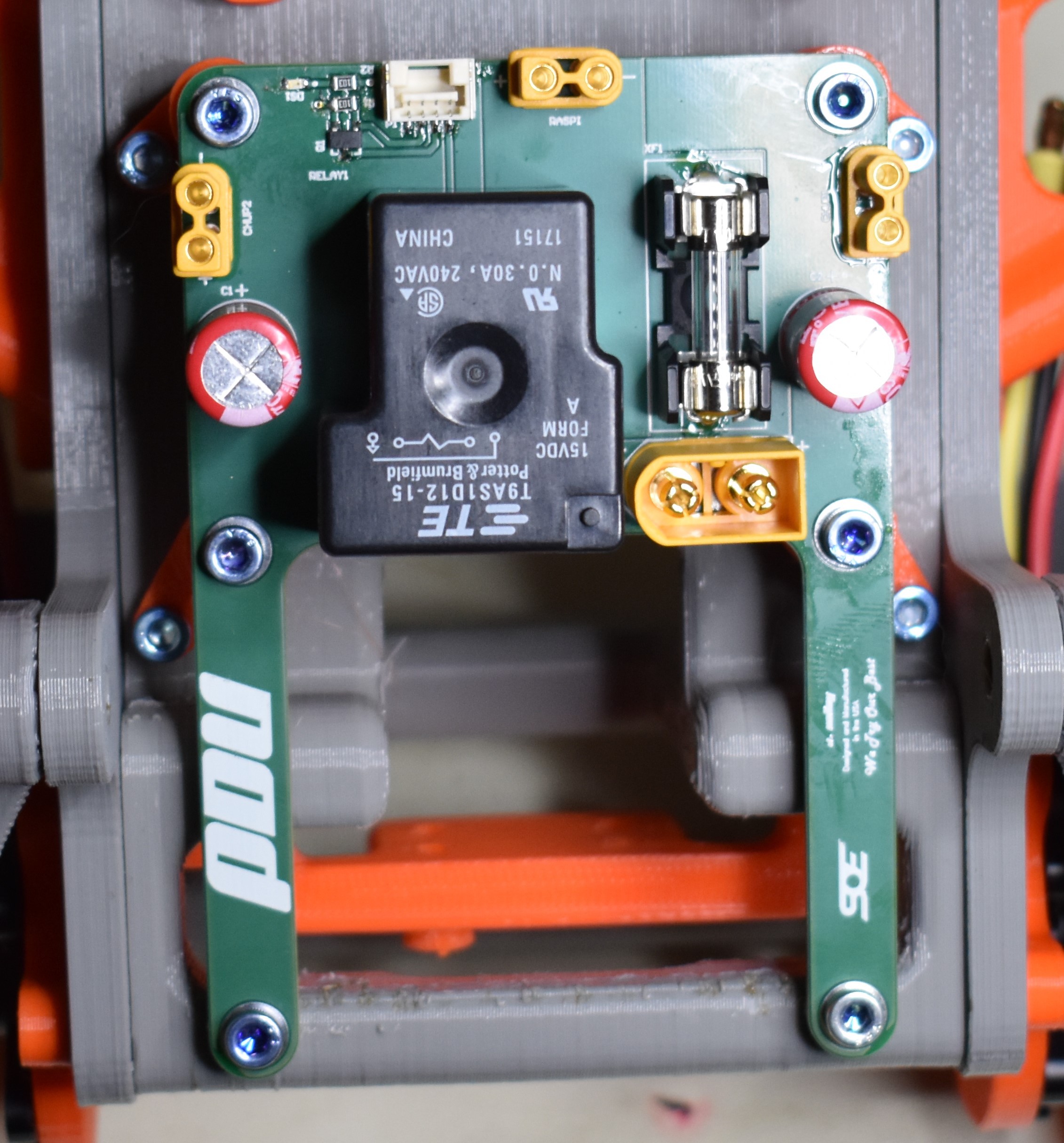
The first PDU is on the newly printed parts, ready for some functional testing! After that, it'll be time to make cables and get everything wired up.
Bobble on,
James
Discussions
Become a Hackaday.io Member
Create an account to leave a comment. Already have an account? Log In.
Ha, recognized that XT60 footprint immediately. Nice build!
Are you sure? yes | no