• Reverse engineering the keypad

    Alessandro05/02/2019 at 22:12 0 comments

    I had my time completely occupied by lectures and exam, but today i finally found some time to continue from where I left off: understanding how the keypad works.


    Smelting the problems away

    Due to the age of the device, I wasn't able to get any output from the keypad, and the metallib back panel was held tight to the body of the device by some plastic pegs (which were still part of the body) molten and pressed tight against the back pane.
    Clearly, getting access to the inside would be a destructive endeavour, right?
    Well that's what I thought, but by heating the tip of a needlenose plier, I was able to elongate those molten rivets back into the original shape (mostly).

    [There should be a photo here, but I totally forgot to take one before hand]


    In the belly of the beast

    After prying the metal backplate, I was able to finally get access to the rubber membrane and the flexible PCB.
    I then proceeded to scan that circuitboard with my printer and this is the result

    All I had to do then, was tracing by hand all the trace with different colours, which took almost 3 hours (trust me, the design is really convoluted on this one).

    I've published a .pdn file (compatible with the Paint.net software) with all the individual traces, color coded and divided in layers.
    Here's a table with the button and their corresponding pin on the connector, nubmered 1 to 13 from left to right:

    1
    [4 , 7]
    2
    [4 , 8]
    3
    [4 , 9]
    R
    [2 , 7]
    4
    [5 , 7]
    5
    [5 , 8]
    6
    [5 , 9]
    Mute
    [1 , 10]
    7
    [6 , 7]
    8
    [7 , 8]
    9
    [8 , 9]
    Enter
    [4 , 11]
    *
    [3 , 7]
    0
    [3 , 8]
    #
    [3 , 9]
    Memory
    [5 , 12]
    M1
    [4 , 13]
    M2
    [4 , 12]
    M3
    [5 , 13]
    Redial
    [2 , 9]

    The weirdness of this keypad matrix knows no bounds.

    I've looked at this nice keypad matrix decoder IC from Texas Instruments, but i'm thinking about making my own with an atmega of some sort because of the pin arrangement.


    Wrapping all up

    After cleaning the contacts, both on the flex and on the rubber pad to improve conductivity, the only thing I had to do was putting everything back the way it shound and then riveting back the back panel by heating the tip of a flat screwdriver and compressing these plastic pins.
    Here it is, like new...

  • PCB analysis

    Alessandro04/23/2019 at 12:40 0 comments

    After long study nights and exhausting exam sessions, I finally found some time to get started on the attempt to design the PCB from scratch.

    The original PCB from Bang & Olufsen is a beautiful single layer board with no SMD parts whatsoever.

    Original PCB top
    Original PCB bottom

    My board is not working, and on top of that, the backup AA battery went off a long time ago, and as a result, the bottom part of the PCB is corroded as well.
    As you can see, there are two switches on the top. On a sticker on the bottom of the phone, the right one has 3 states, labeld from two to zero, and the right one has two states: IWV and MFW

    Needless to say, I have no idea what those switches do.


    After measuring the board in all of its dimensions, I then recreated the board geometry on EasyEDA.
    The board interfaces to the various component of the phones through connectors, which I think require two B2B-ZR sockets for the two microswitches that open and close the call, one B3B-ZR socket for the volume potentiometer and a Molex KK style socket for the loudspeaker.
    Here's the mockup:

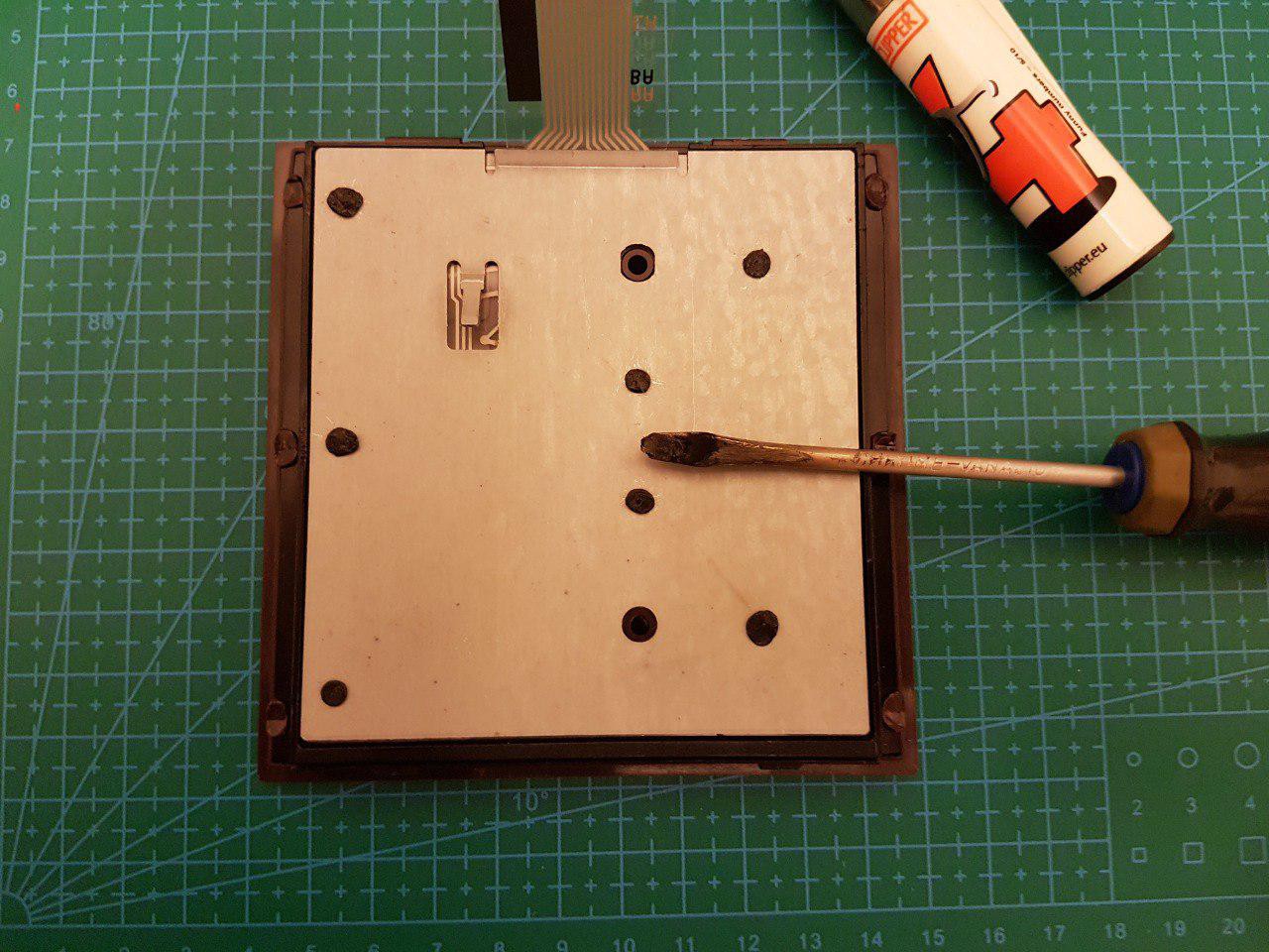
    Speaking of the close and start call switch, the beocom 600 uses two microswitches under the phone hanger: when the handset is hanged, the black switch is closed and the brown one is opened, and when lifted, the black switch opens and the brown one closes.
    The MCU can be then programmed to use both of those switches to start and end a phone call.
    Here's a picture, so you can see the white lever pushing on only one swith at a time
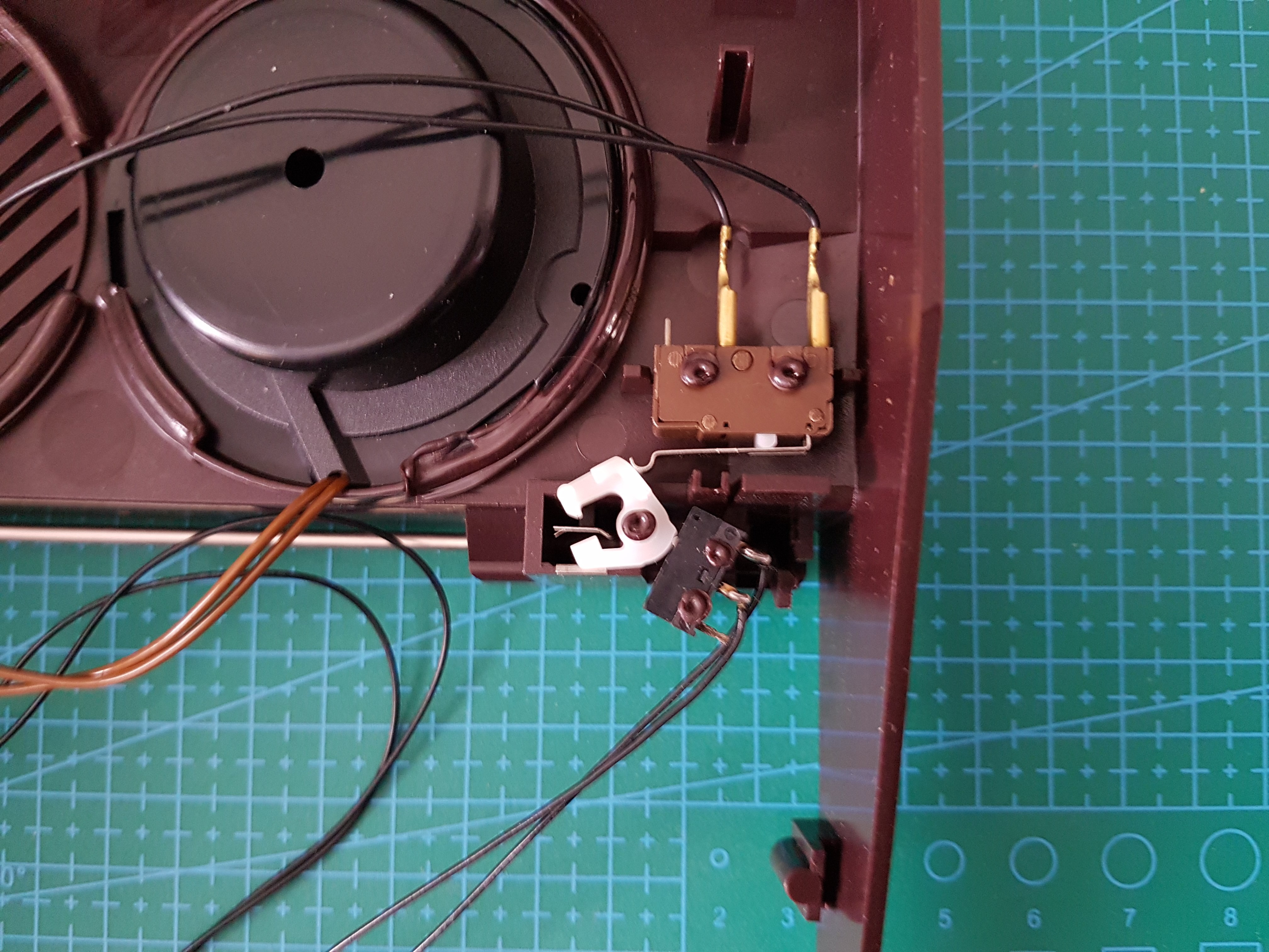
    (As you can see, almost everything is welded to the chassis itself, rendering any attempt of further teardown destructive.)


    The only big problem though, is the keypad ribbon connector.

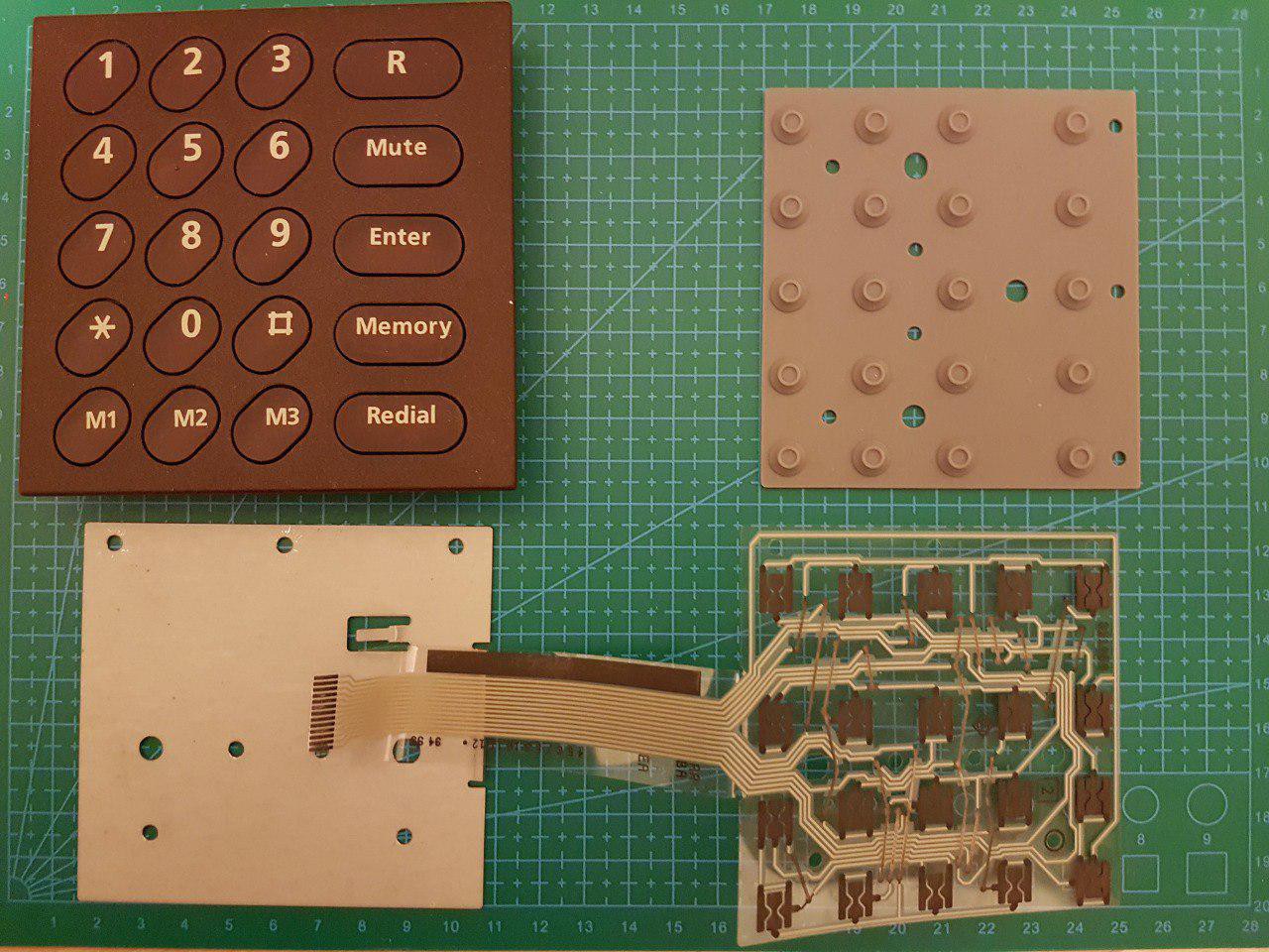
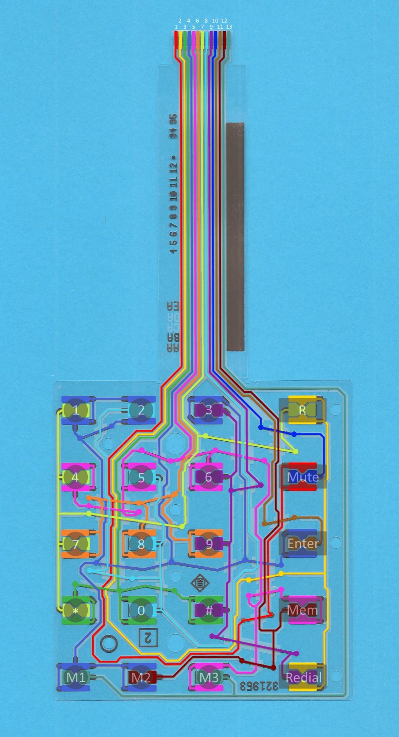
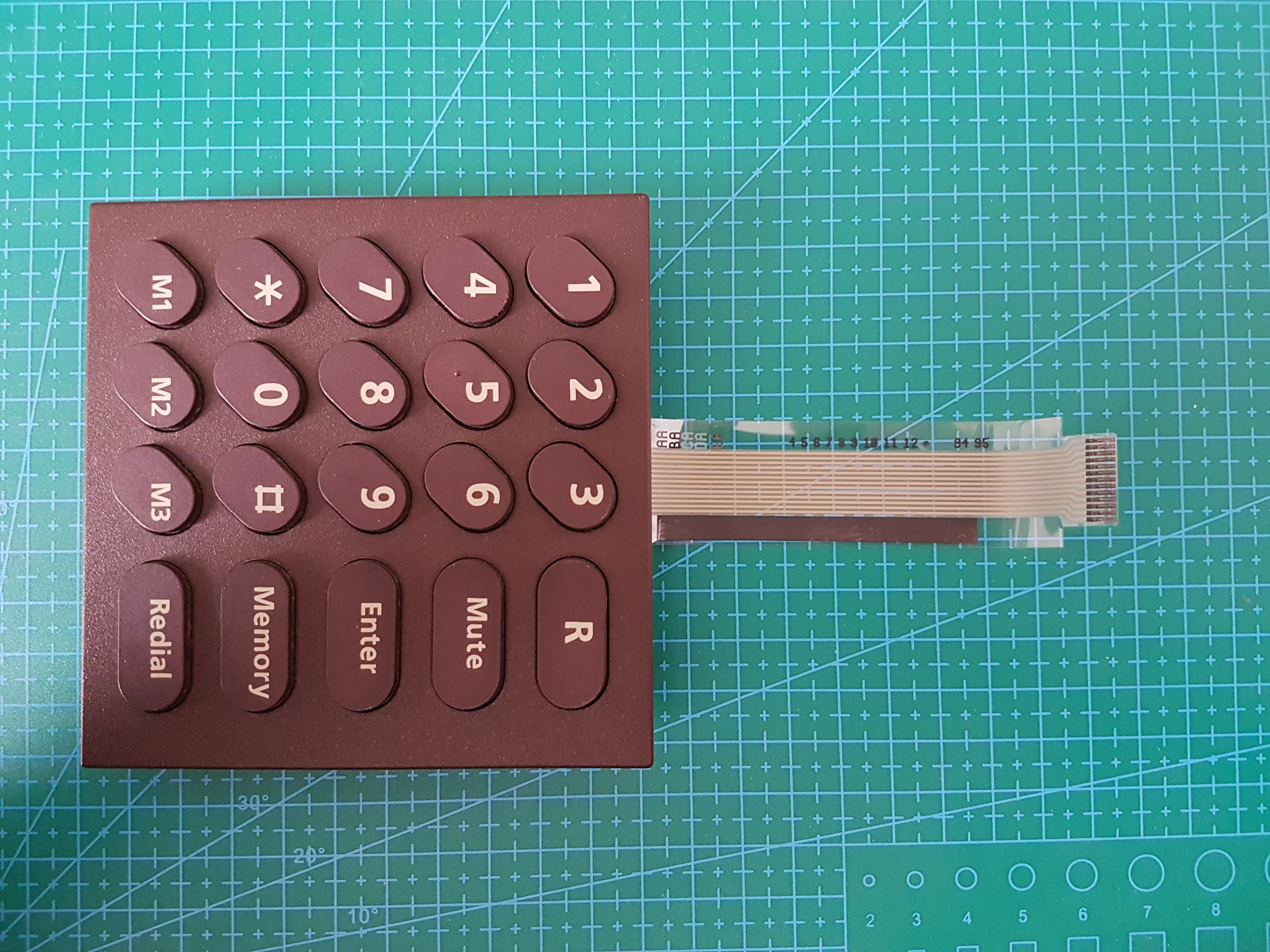
    The keypad is a 5x4 matrix, but it has a 13 pin connector. Probably some pins are not connected, but reverse engineering of the keypad will be the next step.
    Right now, i'm having issues to find the proper socket.
    You can just desolder the one on the original PCB and call it a day, but the aim of this project is to make a replacement PCB that won't require any component transplant From the original B&O PCB.

    As usual, if you have any suggestion either for a suitable and cheaper bluetooth module or for the flat cable stocket, fell free to leave a comment on the discussion section

  • Starting off

    Alessandro04/16/2019 at 13:36 0 comments

    I am trying to figure out what kind of microcontroller (or even SBC) to use to make this project a reality.
    I was really inclined to base this project around an RN52 bluetooth module, but due to the (relatively) high price, I'm looking for another candidate (maybe an ESP32?)
    If you have any ideas, please feel free to leave a comment, I do really appreciate any help :)

    The main scope of this proejct is to:

    • Be able to use the integrated keypad to input a phone number
    • Play a ringtone on the Beocom's loudspeaker
    • Be able to answer a phone call by lifting the receiver and to terminate the call by placing it on the holder
    • Be able to use the mute key to stop the ringtone (without closing the call) or to mute/unmute the microphone while in a call
    • Be able to reject a call by pressing the R button
    • Be able to use the integrated linear potentiometer to adjust the ringtone volume
    • Be able to redial the last number by tapping the redial button

    These are the minimum functionalities I want the replacement PCB to perform to make the project a success.

    Other thing that would be nice to implement would be:

    • Reproduce the appropriate DTMF tone when pushing a key
    • Be able to hear the call via the loudspeaker
    • Be able to speak the calling number or contact when receiving a phone call (this would basically require a TTS engine and probabily require a small SBC)
    • Respect the "do not disturb mode" of the phone
    • Be able to store 3 numbers in memory to speed dial them by using the M1, M2 and M3 keys 9