 deʃhipu
This is not my first encounter with those small OLED display modules. We actually go back a while.
First I tried to use it for the #Micro:Boy project, and I kept failing to get it working so much, that in the final version I decided to just use one of the ready modules. And of course after I did that and redesigned everything, I came back to the initial project and discovered that the display itself was physically faulty. But the project moved on, and I discovered other reasons why it won't work (not enough memory and code space on the micro:bit for the kind of games I wanted).
Second attempt was with the #CircuitPython Badge, where one of the prototypes I've build used that display. I used the same display module, but in 4-wire SPI configuration this time. I wasn't able to get it to work, and I've moved on to e-ink displays, and later, after rethinking the whole thing, to LED matrices, because of the specifics of the project (the display needed to be big, not necessarily high-res).
And here I am again, with the accursed display, in 4-wire SPI mode again. And again, I looked at the application notes in the datasheets both for SSD1306 and for SH1106, I looked at Adafruit's schematics for their breakout, and I am none the wiser. The connections are exactly the same as on that badge, and there is really nothing wrong with them, at least as far as I can see. Sure, all three sources of data use wildly different values for the capacitors — from 1µF, through 2.2µF, up to 4.7µF and 10µF. So which ones are correct? Who knows? Will the display work with my new PCB, if it didn't with the old one? Will I ever be able to get those things to work?
Facing all those questions and doubts, I decided to take arms against them, and answer them once and for all. I dug out of my drawers the failed badge prototype, and decided to try and get it to work. I started by finding the designs files for it, and re-creating the board definition for CircuitPython, so that I can use the latest version (it includes displayio module, which I will need to get to work with those OLED displays later on). Then I flashed it, and dug up some of my old libraries for MicroPython for this display, and quickly converted it to CircuitPython. A quick test, and of course it doesn't work. Dead.
Fine, as a next step, I tried all three combinations of capacitor values. No difference. Measured the voltages on those caps — hmm, looks like the charge pump is not even starting...
I de-soldered the display from the prototype, and from a known good breakout, and swapped them. Tried the breakout module with an Adafruit board I had lying around, using Adafruit's SSD1306 libraries. Ah-ha! The display did start, but it's an SH1106, not SSD1306. But it's not faulty, so it should be at least showing something, like in this breakout. Why doesn't it?
Next I tried the display from the known-good breakout in the prototype, with the code I had on it. Nope, doesn't work. And I'm sure this one is an SSD1306 and working. So something is wrong with the prototype. The charge pump is not switching on, so perhaps something with communications?
I checked the continuity for all the control pins — everything looks correct. I re-soldered them, just to be sure. Still nothing. It seems that physically everything is fine...
Wait a minute, what if I used those Adafruit libraries on this prototype? I copied them over and lo and behold! The display works! It was my crappy code all this time!
I re-soldered all the displays back to their places, and changed the init sequence to a minimal example from my tutorial — just enabling the charge pump and setting contrast.
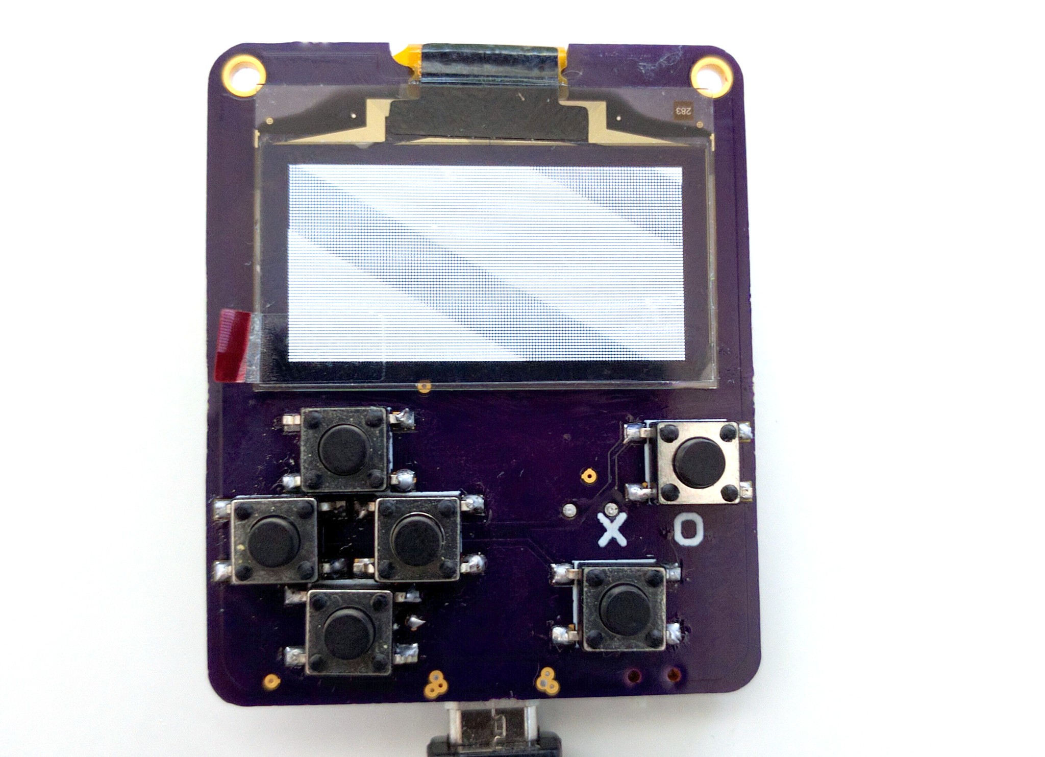
And it works perfectly fine (the pattern on the display is the refresh of the OLED interfering with my potato camera).
That means not only that the PCBs I ordered are going to work, but also that I can already start testing code on this prototype.
Discussions
Become a Hackaday.io Member
Create an account to leave a comment. Already have an account? Log In.