 Scott Swaaley
SUMMARY DESCRIPTION:
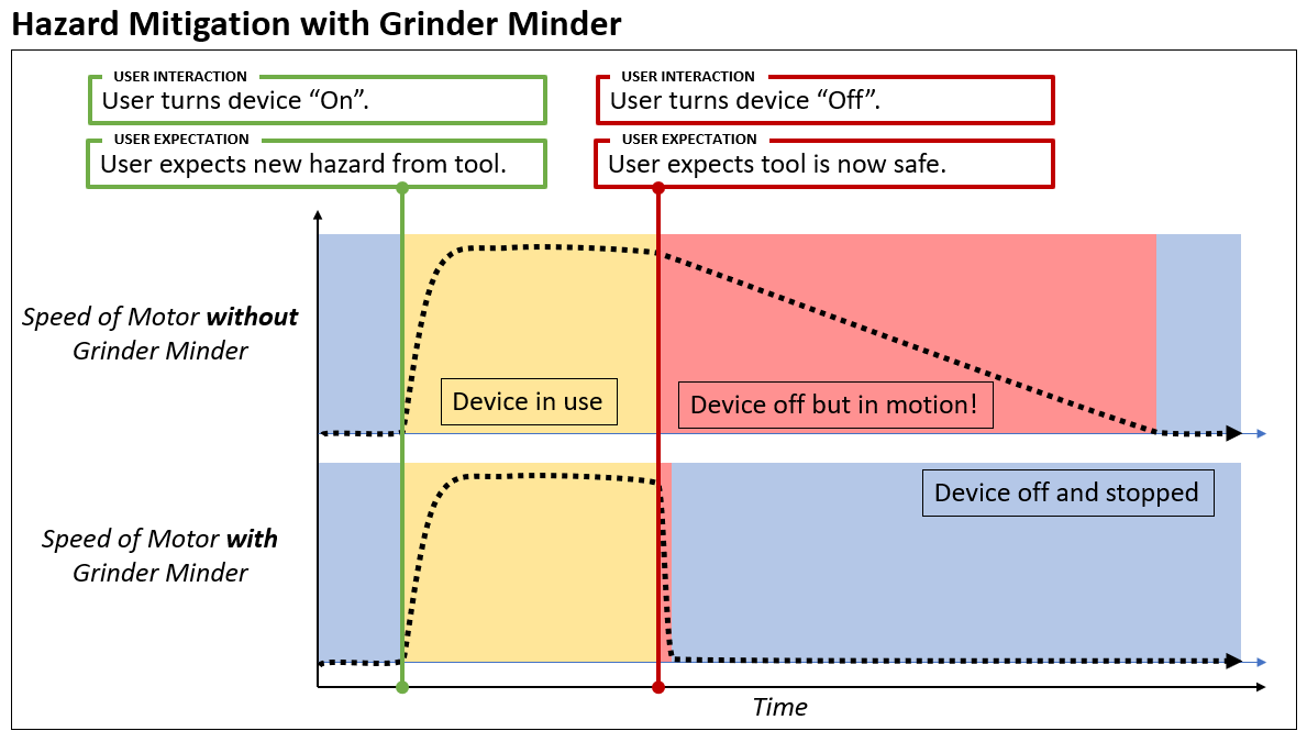
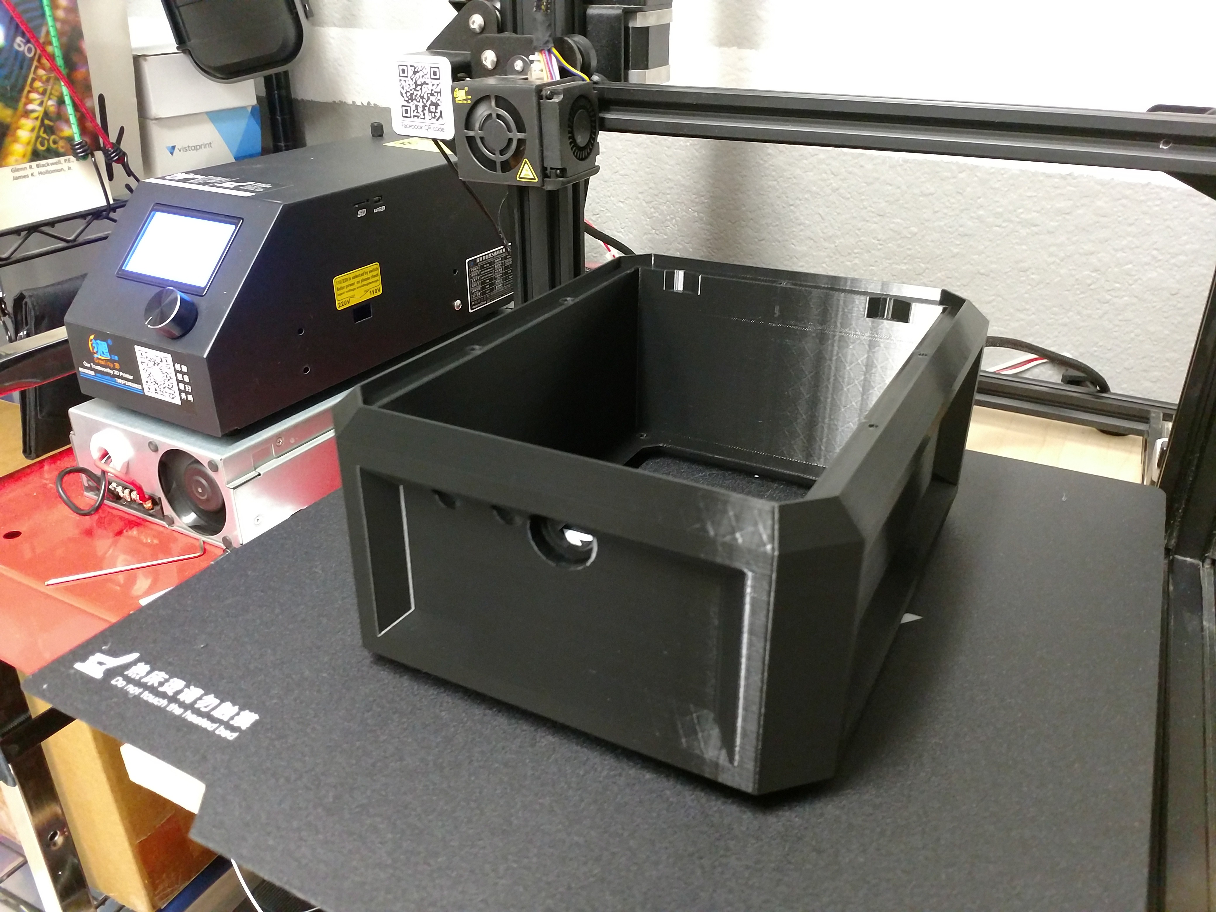
Tools like stationary grinders can continue to spin for two and a half minutes after being powered off, presenting an enduring hazard to the operator and nearby individuals. Worse, operators tend towards the mindset of "it's off therefore it is safe" which the coasting problem proves alarmingly false. Grinder Minder's primary purpose is to act as a drop-in control replacement with automatic braking minimize the chance of an off tool being dangerous and does so in three different ways (detailed below).
THE CHALLENGE WE'RE ADDRESSING:
Every day, millions of people work around and with motorized machinery and tools. Many of these tools sport flywheels, heavy tooling, work-pieces, or other large mass components. And since inertia is a property of matter, when these tools get spinning, they don't like to stop just because someone turns off the motor. A grinder, for instance, can spin for up to 2.5 minutes after power has been removed. Despite these machines being nearly as dangerous in that time as they were when powered, people will often act as though "Off" means "Safe". As you might expect, the collision of this misconception with the reality of fingers, clothing, or hair getting caught in moving machinery leads to serious injuries.
HOW WE'RE ADDRESSING THE CHALLENGE:
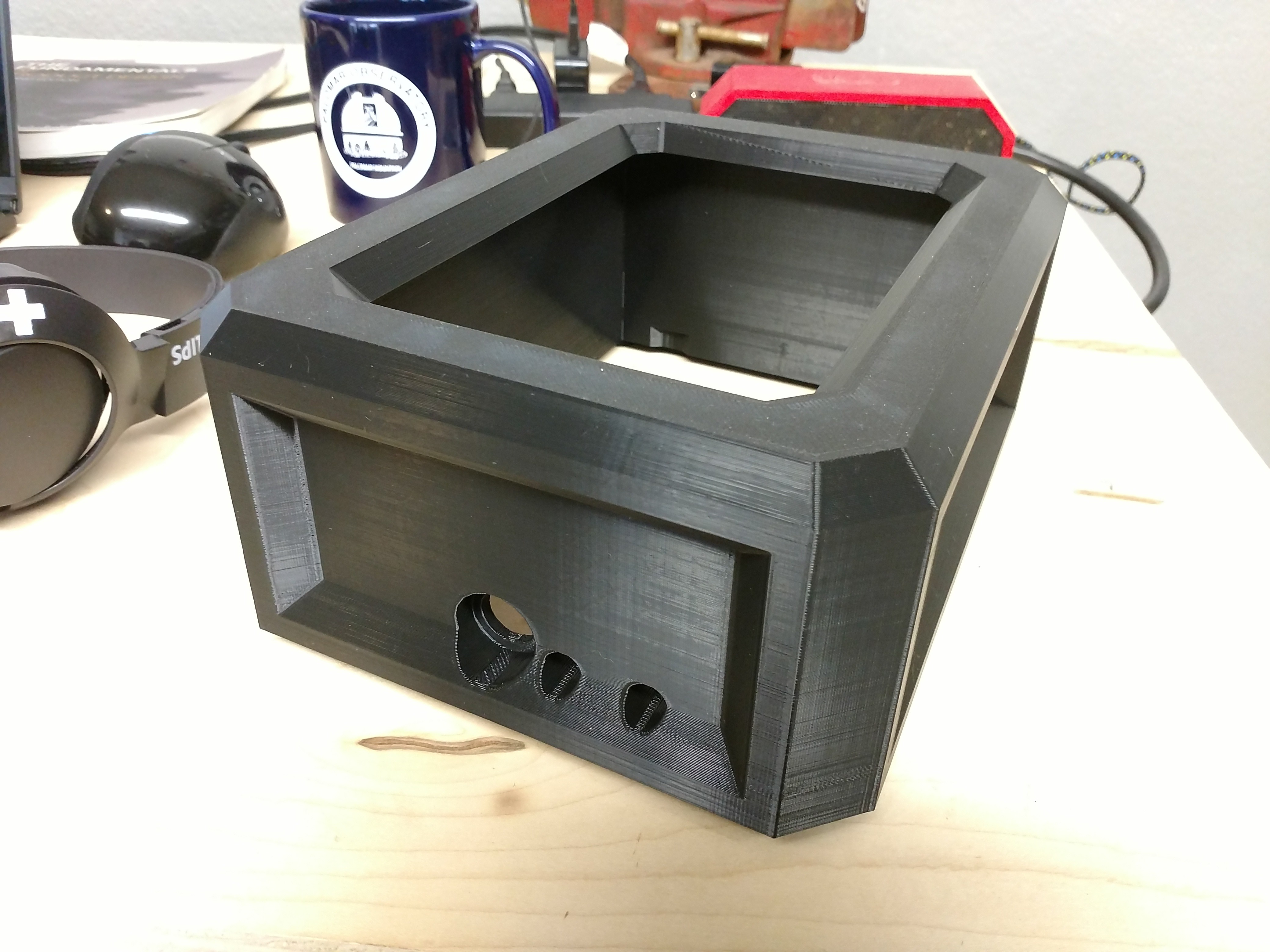
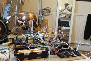
Our solution turns "Off==Safe" into reality, instead of misconception. By replacing the user interface and supplementing control circuitry, all in a "plug-and-play" package, our device brings the motor to a rapid stop, creating a safe environment without requiring each user to change their workflow or habits. And because this solution requires control circuitry, we were able to implement three highly sought after safety features:
- Automated tool braking to close the gap between "Off" and "Safe"
- Accidental-restart prevention to keep your device from starting unexpectedly in power failure situations like a tripped and restored breaker
- Access Controls to give you the ability to regulate who can use the tool (a key switch)
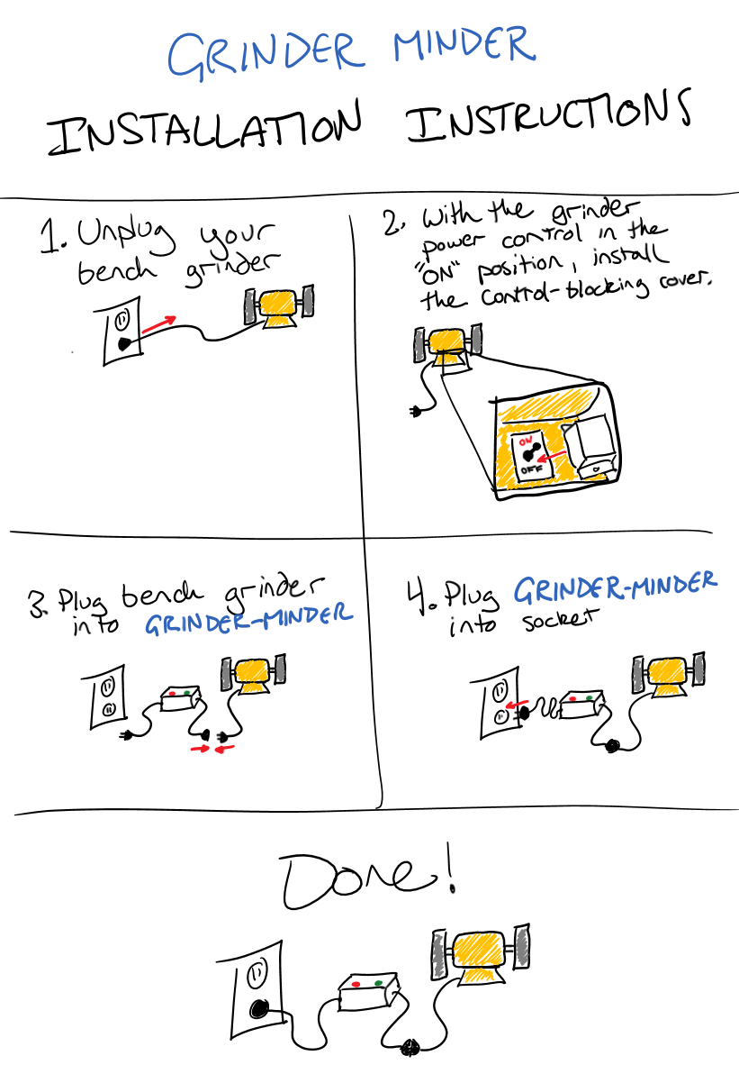
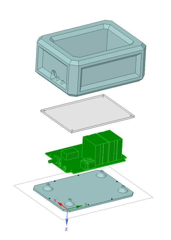
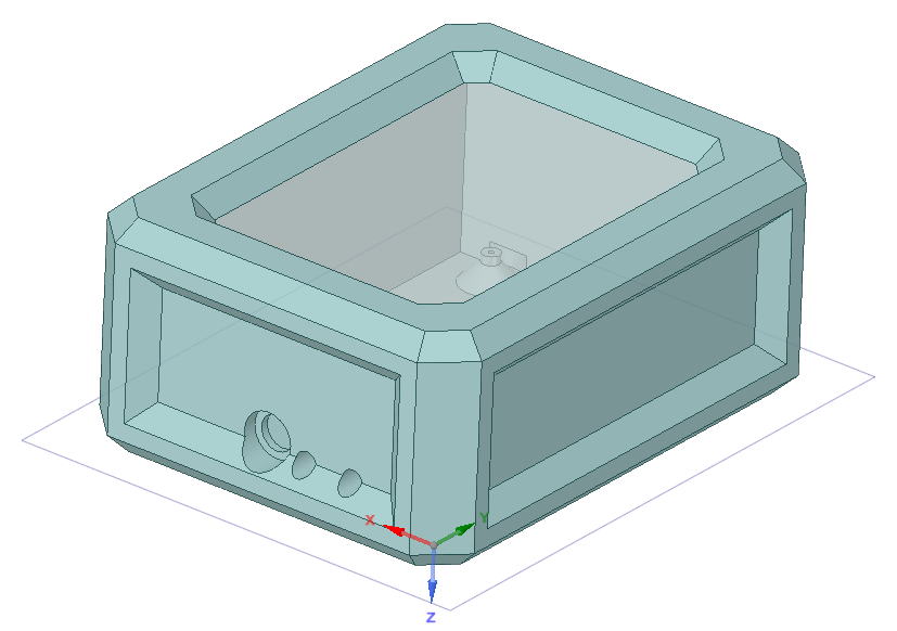
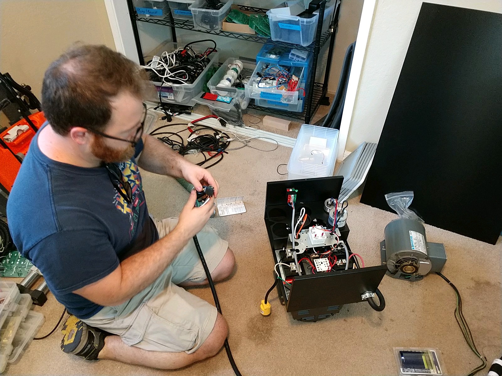
HOW THE SOLUTION IS USED: (Installation, Operation, Calibration)
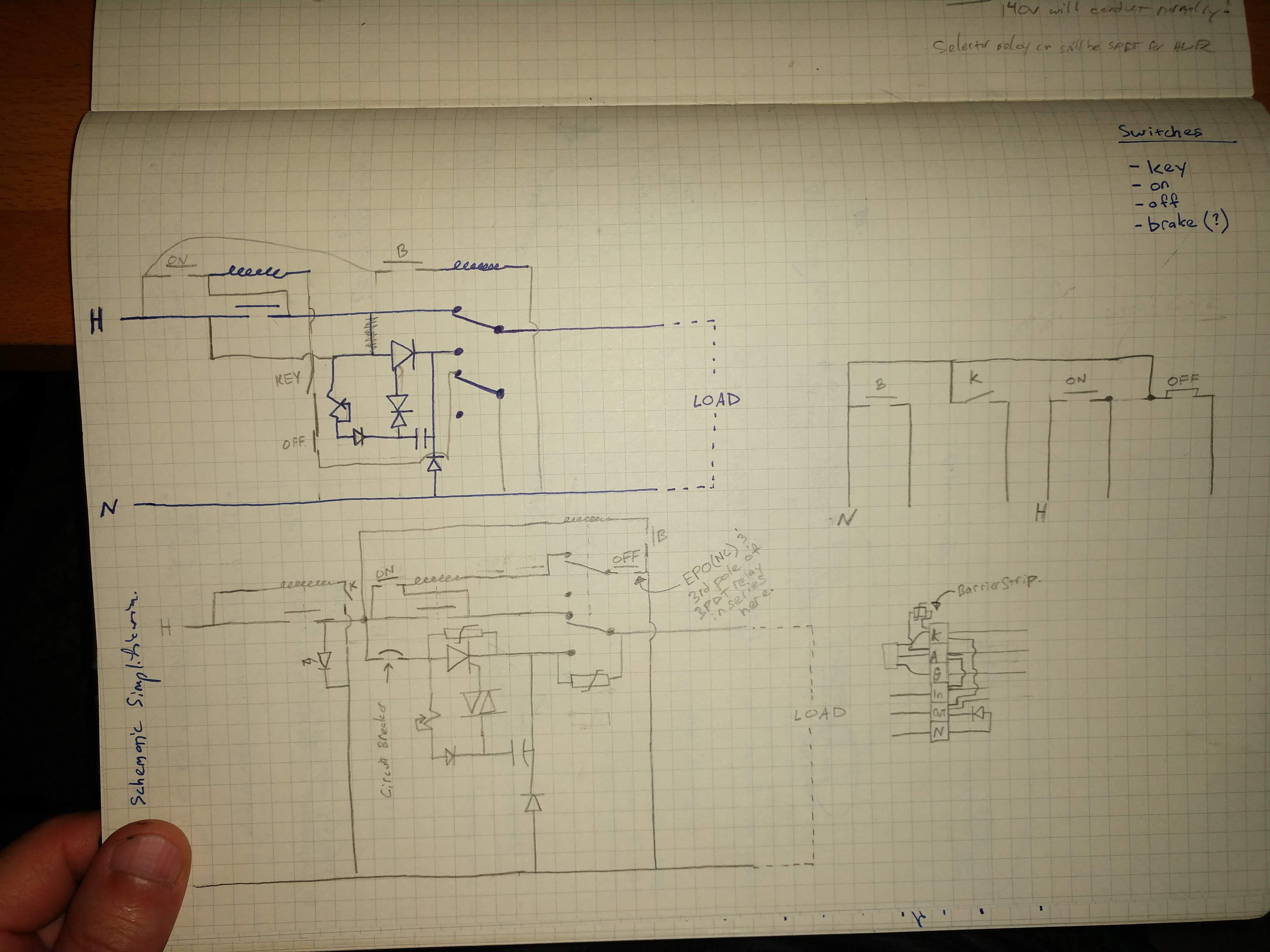
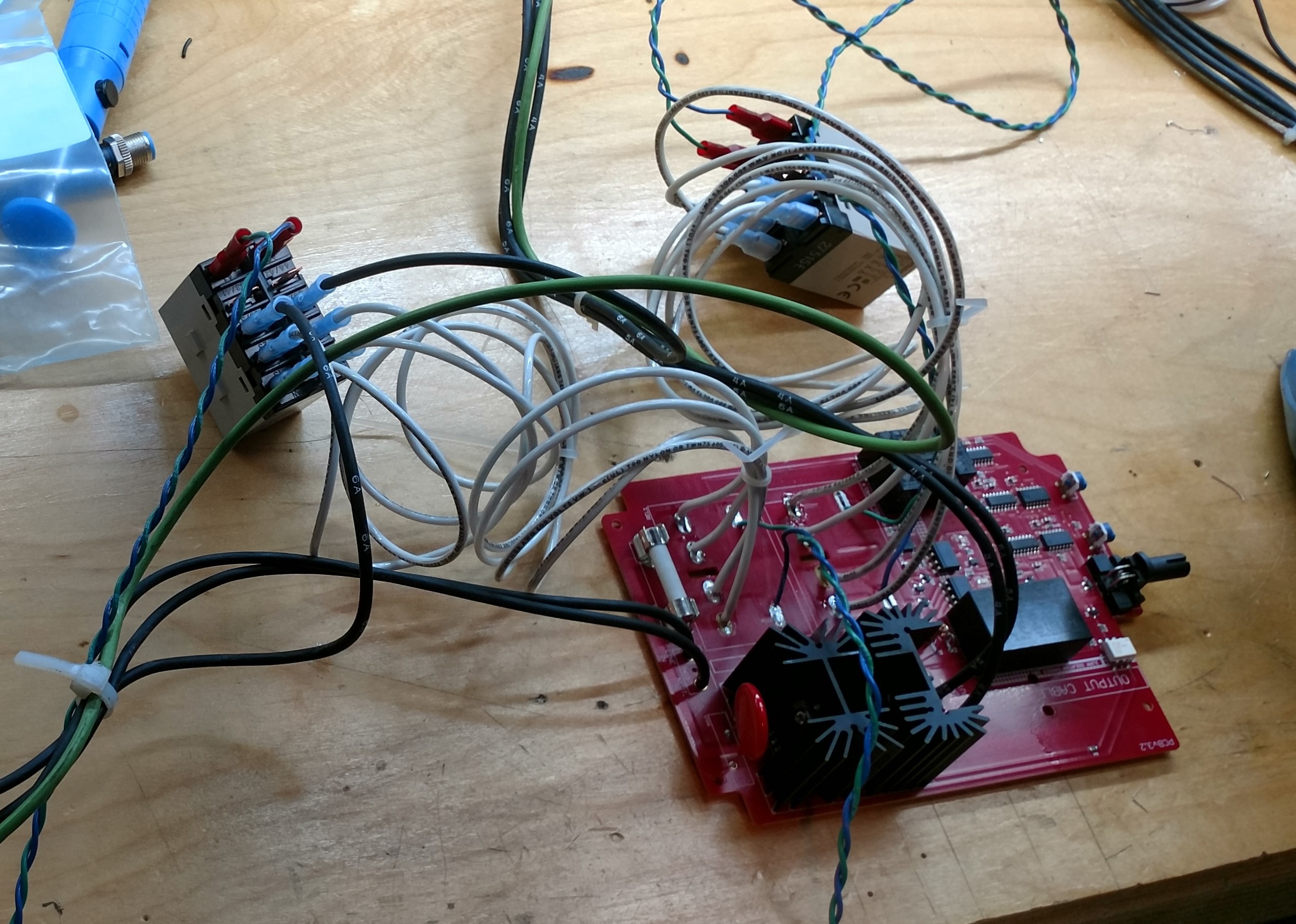
SOURCES AND SCHEMATICS:
Project sources and schematics will be shared as attachments in this project page.
LICENSING:
Each file's license will be added in the file's description.
PROJECT SCOPE:
Device Class:
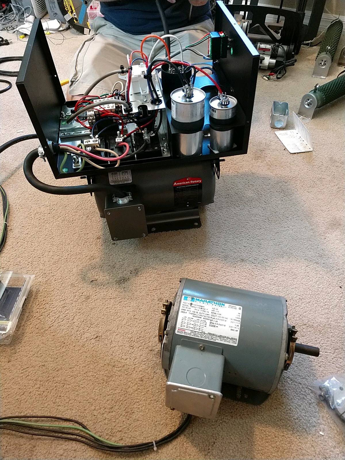
While the circuit itself could be expanded to handle any device with an induction motor, creating and testing a circuit across so many devices would have been difficult for the 2019 HackADay Prize competition. To narrow the scope, we focused in on a commonly found and high-inertia device: the grinder.
Customer:
Our original customer focus was around consumers and hobbyists working out of their small shops or garages. We expected that these customers would typically have single-phase consumer grade bench-top grinders, like those sold at Home Depot. This focus shifted mid-project to the opposite end of the spectrum when some customer research and interactions with individuals in the safety industry expressed a strong interest in much larger commercial 3-phase grinders.
PRODUCT FEATURES:
We identified some core features which we felt would be necessary to satisfy our customer group:
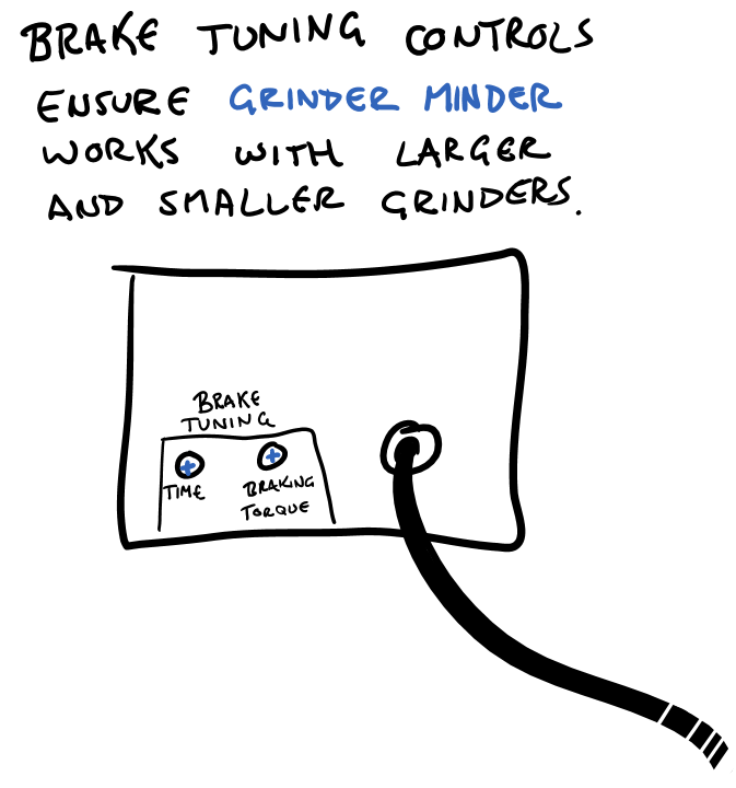
- DC Injection Braking - to stop the tool quickly after each use thus preventing injuries associated with coasting. This requires the supply of up to 5kW of DC power delivered for up to 4 seconds.
- Accidental Restart Protection - to prevent the startup of the tool in the event of power loss or accidentally leaving the power switch in the 'on' position.
- Emergency Stop - an ANSI-compliant emergency stop button to activate braking in the event of an emergency.
- Drop-In Installation - designed so installation requires nothing more than plugging it in in-line with the...


 CriptasticHacker
 Alex Dunnett
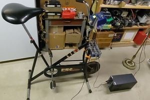
 alnwlsn
Meat is an inherent part of the non-vegetarian’s diet. And we love making new recipes and eating them. Especially beef, ham, and chicken are the common types of meat to use in everyday life Best Meat Grinders for Deer. But one of the drawbacks of consuming these meats on a regular basis is that they are rich in fat.