Close
0%
0%

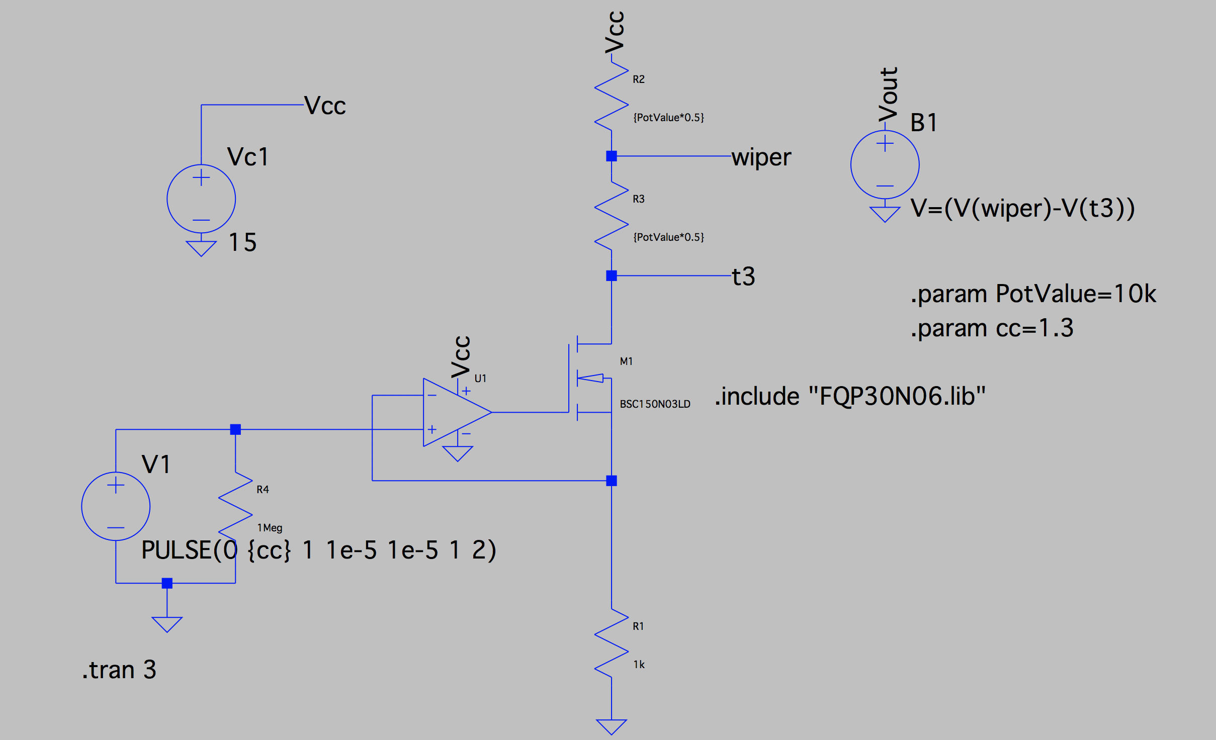
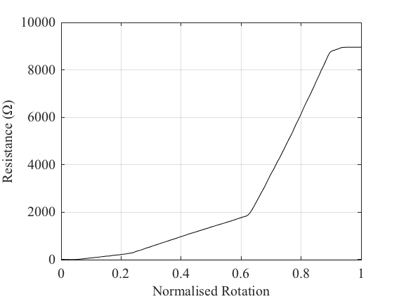
Spin/Drive: Automatic potentiometer tracer

An electromechanical measurement system for tracing pot characteristics.

Similar projects worth following
When modelling musical circuits - for prototyping or real-time simulation - a core aspect of the circuit is how it changes in response to the user twiddling its knobs. To make a complete model it is therefore necessary to get an accurate model of the potentiometer.

This project utilises an Arduino which drives a stepper motor to automatically rotate a potentiometer while its resistance is measured. A voltage controlled current source is used to drive a known current through the potentiometer while measuring the voltage across two of its terminals. The measured voltage can be divided by the current to find the resistance.

PotentiometerRotate.ino

Arduino code for rotating the potentiometer in response to a trigger.

ino - 2.59 kB - 04/17/2019 at 11:54

Download

  • 1 × Stepper Motor, 12 V, Bipolar https://www.sparkfun.com/products/9238
  • 1 × Adafruit Motor Shield for Arduino v2 https://www.adafruit.com/product/1438
  • 1 × Arduino Leonardo Uno and other boards may work too
  • 1 × NI myDAQ The data acquisition tool used to measure voltage and trigger the pot rotation.
  • 1 × Voltage Controlled Current Source A DIY circuit for converting voltage to current.

  • Initial results with a VCCS

    Ben Holmes04/23/2019 at 08:22 0 comments

    The demonstration video uses the analog input to the Arduino to measure the voltage ratio of a potentiometer, which while providing the underlying characteristic of the device, does not provide the resistance of the pot.

    By driving a known current through the potentiometer, the voltage between two terminals can be measured to find the corresponding resistance. A simple VCCS can be made with an op-amp and a MOSFET, mocked up in LTspice:

    This circuit also enables pulsing of the current to prevent heating of the potentiometer, further improving accuracy of the measurements.

    Limitations lie in the range of resistances that can be measured. Following Ohm's law, as the total resistance of the potentiometer increases the current that must be driven through the device must drop in order to produce a voltage that can be measured within the limits of my DAQ. Driving smaller currents increases the circuit's sensitivity to noise and voltage offsets, requiring more thought on how to achieve good performance.

    For a 10k pot this circuit appears to work pretty well though! Here is a rough measurement of a device:

    The pot is clearly 10% off at the maximum resistance (which is within spec). At 50% rotation the device can be seen to be 15% of the total spec'd resistance. This parameter is often used to differentiate between different logarithmic laws, as can be seen on the Alpha website.

View project log

Enjoy this project?

Share

Discussions

jean.kagian wrote 01/05/2021 at 05:42 point

Hi, I just joined Hackaday because of you!  I really want to build this.  I've gone down the rabbit hole of pots and let me tell you, it goes deep.  My interest is figuring out what pots the manufacutrers are using when they build simulation gear (racing pedals, throttles, joysticks...).  The problem is that these manufacurers do not want you to replace the pots when they fail (and fail they do).  This is a "right to repair" issue for me.  Some have gone so far as to remove the markings or have custom codes printed on the pots so that you have no choice but to go back to them.  If you're using a PC, no problem.  You can replace it with one that is close enough and the calibration software will map out your 0-100%.  However, if you're using a console like a Playstation or Xbox, you're out of luck.  There is no calibration option.  You need to find the exact pot with the exact specs.  This is what got me started down the rabbit hole.  I recently decided on a late career change into Industrial Electronics/Electricity/Automation.  I'm about halfway done my course.  A friend of mine was complaining about his inability to replace/upgrade his pots and I told him "it can't be that hard".  I was wrong!  So now, I need to figure out the ohms, the degree of turn, in/out voltage, torque needed to turn it and whatever else.  I pretty much have to start from the pot and figure out the full spec sheet.  So, looks like I'll be standing on your shoulders.  Thanks for this!  I'll keep you posted in the coming months.

  Are you sure? yes | no

Mike Szczys wrote 04/22/2019 at 16:18 point

This is very cool. Do you just test the pots until you find the one you need, or are you tweaking other components in the circuit to help trim up the trimpot?

  Are you sure? yes | no

Ben Holmes wrote 04/23/2019 at 08:06 point

The characterisation isn't really for circuit design, people tend to chuck these into pedals and other circuits without much thought.

I'm trying to build up a bit of a database of different potentiometer characteristics so that modellers have a reference for what they might look like. There is a big field of simulating audio circuits for musicians, live and in studios, and I believe this a (small) step towards making sure that these emulations replicate a circuit's warts and all!

  Are you sure? yes | no

Similar Projects

Does this project spark your interest?

Become a member to follow this project and never miss any updates