 Antoine Pintout
Once I had the functionalities well defined for each of the three devices, I started to prototype, or more accurately, sketch each of my devices on breadboards. The firsts consisted just of cheap knock-of Arduinos with buttons, LEDs and the few specific actuators or sensors I needed. It was great to test each device in a controlled way. But I needed to be closer to an actual circuit that I could put on a PCB no bigger than a hand palm.
The next step was to get rid of the Arduinos and get instead a bare ATmega328. I redid my circuits using a mix of bare chips "dead-bugged" and breakout circuits from Adafruit, Sparkfun or NavSpark.
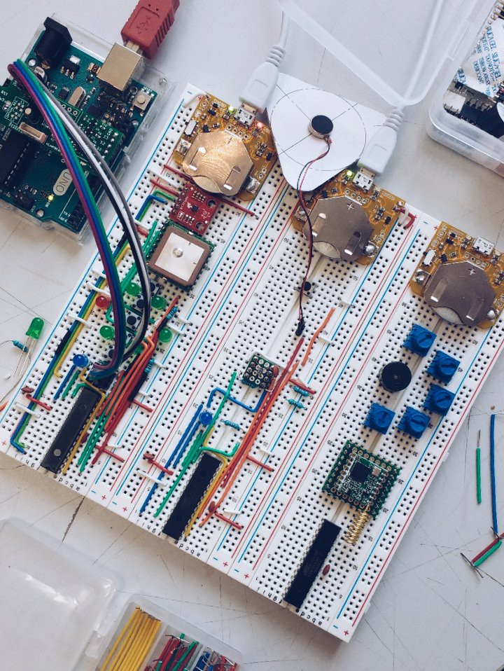
I also prototyped a charger circuit for the LiPo I wanted to use. This PCB conveniently fitted very well on the breadboards. You can get it on the this repo : LiPo Charger.
I tried to have an aesthetically satisfying cable management as I knew that I may have to show it here. I associated color with function : blue if for the clocks, yellow for reset, orange for interrupt sources, green for data, and red/white for power.
You can see that i glued my vibration motor to some cardboard to try to feel what a vibration would be like. I ended up cutting all my shapes onto cardboard to figure out an ideal shape for each device.
To flash the ATmegas, I remixed one of my previous projects : a Arduino UNO hat that breakout ISP signal with a proper voltage level shift. Indeed, I figured out that I needed to work at 3.3V instead of the standard 5V for classic Arduino boards. This ended up causing some problems, but thanks to that setup I could quickly figure out what went wrong.
One of the problems I had was that high speed SPI between one of my sensor and my MCU was not working. At the time I didn't know that the SPI bus was the cause of the malfunction. But a quick detour to an oscilloscope showed me that the signal was not reaching the high threshold. I figured that the pull-up resistors used by default on a Sparkfun break out were to large. This was an amazing learning opportunity as I was able to test multiple resistor values and immediately see the consequences on the signal.
I settled on a value of 1K. This may not be ideal, as it may increase power consumption of the whole device. But this is not the time for optimisation. This was the only oscilloscope of my school, but nobody used it, so I kept it. It saved me lots and lots of time in the development process (I returned it at the end of the semester =) ).
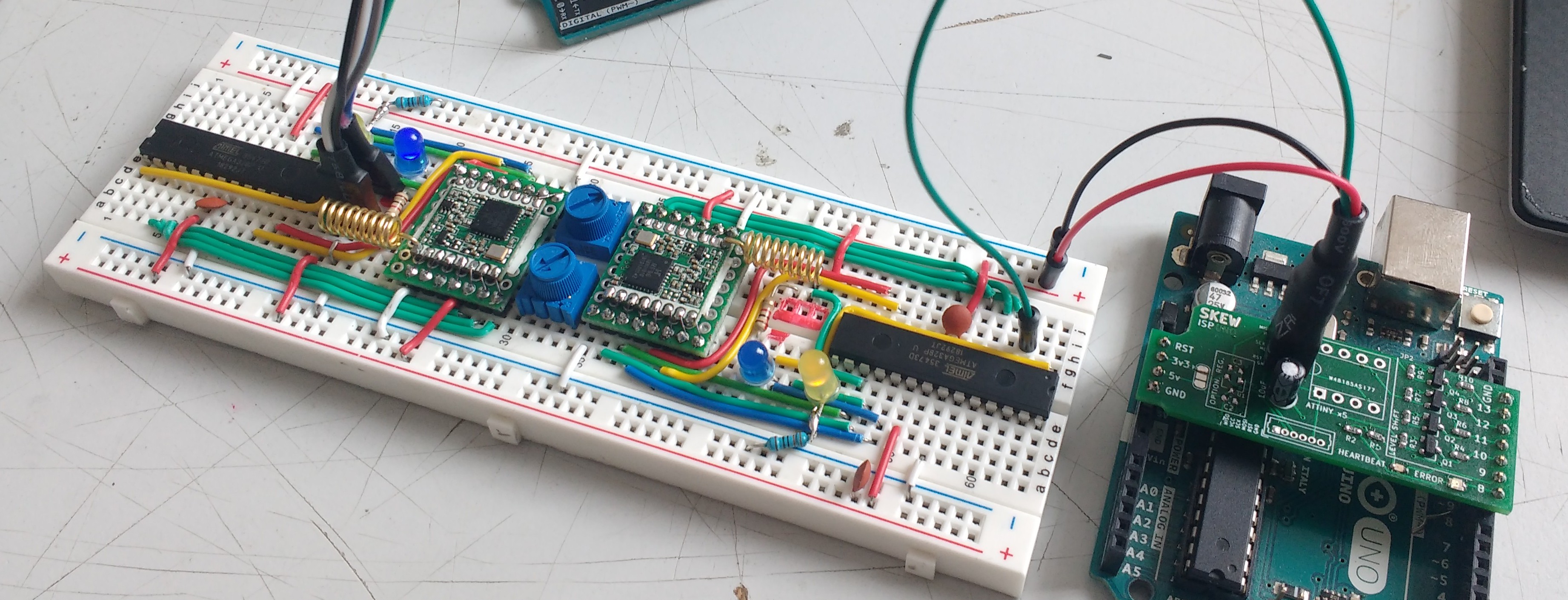
I finally did a dual one so I could work on the LoRa modules outside of the studio where all my project was. You can see that the hat I made was also used to get some power in and some UART serial out of the ATmegas to my computer for debug purposes.
With this setup, remixed several times to accommodate new sensors, I got a better idea of the real estate I needed from my PCBs and how small my devices could be. I ended up using those to develop the base of the my firmwares, as the electrical circuits should be no different from the PCB I draw and ordered.
With all the interfaces and sensors/actuators figured out, I was able to go to a mechanical validation phase. But that is for the next log !
Until next time,
be good !
Antoine
Discussions
Become a Hackaday.io Member
Create an account to leave a comment. Already have an account? Log In.